What is Threshold Crossing Height (TCH)?
Threshold Crossing Height (TCH): Aviation Glossary
Definition and Core Concept
Threshold Crossing Height (TCH) is the calculated height above a runway’s threshold where an aircraft’s glide slope antenna passes when following the published ILS (Instrument Landing System) or MLS (Microwave Landing System) approach path. TCH is a fundamental metric in precision approach design, balancing the need for obstacle clearance with maximizing the usable landing distance. According to ICAO Annex 10, this is known as the ILS Reference Datum Height (RDH), typically set at 15 meters (50 feet) above the threshold, with a strict positive tolerance. TCH is not the height of the aircraft’s wheels or fuselage, but rather the height of the glide slope receiver antenna, usually mounted above and forward of the main gear, when on the precise vertical approach path.
TCH is critical for:
- Ensuring all arriving aircraft clear obstacles immediately before the runway
- Maximizing available landing distance by setting the lowest safe crossing height
- Harmonizing approach procedures for different aircraft sizes
- Supporting automated landing systems and safe touchdown initiation
Authoritative Definitions and Related Concepts
ICAO and FAA Definitions
- TCH: “The theoretical height above the runway threshold at which the aircraft’s glide slope antenna would be if the aircraft maintains the trajectory established by the mean ILS glide slope or MLS glide path.” (FAA Pilot/Controller Glossary)
- ILS Reference Datum Height (RDH): “A point at a specified height located above the intersection of the runway centre line and the threshold and through which the downward extended straight portion of the ILS glide path passes.” (ICAO Annex 10 Vol I)
- Screen Height (SH): “The height of an imaginary screen which the airplane would just clear at the end of the runway, or runway and clearway, in an unbanked attitude with the landing gear extended.”
Comparison Table
| Term | Measures | Reference Point | Typical Value (CAT I) | Primary Use |
|---|---|---|---|---|
| TCH | Glide slope antenna height above threshold | Threshold (runway start) | ~50 ft (15 m) | Approach design, charting |
| Screen Height | Main gear height above threshold/end | Threshold or landing distance | 35 ft (10.7 m) landing, 50 ft (15 m) takeoff | Performance calculations |
| RDH | Glide path height above threshold (design) | Threshold/runway centerline | 50 ft (15 m) | ILS siting, obstacle clearance |
Application in Instrument Approach Procedures
TCH is published on all precision approach charts (e.g., “GS 3.00° / TCH 50 ft”). It defines the vertical geometry of the approach at the threshold, ensuring:
- Safe clearance of obstacles before the runway
- The touchdown point is neither too close to the threshold (risking short landing) nor too far (wasting runway)
- Automation logic for autoland and flare initiation is accurate
TCH also determines the Wheel Crossing Height (WCH): the main landing gear’s height at threshold. Engineers must subtract the distance from the glide slope antenna to the wheels (plus deck angle) from TCH for each aircraft type to ensure safe wheel clearance.
Example: Large vs. Small Aircraft
- Boeing 747: Glide slope antenna is up to 10 ft above and 100 ft ahead of the main wheels. At TCH 50 ft, wheels may cross at ~31 ft.
- Small Jet: Antenna-to-wheel difference is less, wheels cross closer to TCH (e.g., ~47 ft).
Regulatory Standards: ICAO, FAA, EASA
ICAO
- Standard RDH/TCH: 15 m (50 ft) above threshold, tolerance +3 m
- Glide Path Angle: 3.0° standard, can be increased for obstacles/noise abatement
- Wheel Clearance: Ensures at least 8 m (26 ft) for largest aircraft
FAA (TERPS)
- CAT I: Optimum TCH 50 ft, range 20–60 ft, subject to WCH requirements
- CAT II/III: Optimum TCH 55 ft, allowed 50–60 ft
- Displaced Thresholds: TCH referenced from usable landing surface
EASA/JAA
- Generally aligns with ICAO, with minor national variations
| Authority | TCH/RDH Standard | Typical Tolerance | Glide Path Angle | Special Cases |
|---|---|---|---|---|
| ICAO | 15 m (50 ft) | +3 m | 3.0° | Cat II/III stricter |
| FAA | 50–55 ft | +10 ft | 3.0°–3.5° | Cat II/III: 50–60 ft |
| EASA | 15 m (50 ft) | as ICAO | 3.0° | as ICAO |
Measurement and Calculation
- Glide Path Geometry: TCH is set by projecting the glide path angle to the threshold, factoring in antenna location and runway elevation.
- Flight Inspection: Uses flight inspection aircraft or ground-based theodolite to verify actual TCH matches design.
- Aircraft Geometry: The vertical and horizontal offset between antenna and main wheels, plus the aircraft’s deck angle, determines actual wheel crossing height.
Practical Calculation Example
For each extra meter of TCH, the touchdown point moves about 20 meters further down the runway (at 3° glide path).
| Aircraft | Antenna Above Wheels (ft) | Antenna Ahead (ft) | Deck Angle (°) | WCH at TCH 50 ft |
|---|---|---|---|---|
| B747 | 10 | 100 | 5 | ~31 ft |
| B737 | 7 | 40 | 3 | ~43 ft |
| Small Jet | 5 | 15 | 3 | ~47 ft |
Operational Implications
For Pilots
- Always check approach charts for TCH and adjust landing technique for your aircraft type.
- Be aware of the antenna-to-wheel difference, especially for widebody aircraft.
- On displaced threshold runways, reference TCH from the correct landing surface.
For Engineers and Designers
- Design TCH to accommodate largest aircraft using the runway.
- Validate procedures via flight inspection and check for compliance with ICAO/FAA/EASA standards.
- Adjust TCH for local terrain, runway slope, and displaced thresholds within regulatory tolerances.
Airport and Runway Considerations
- Airports with mixed fleets or special terrain may require bespoke TCH values.
- Steep approaches (e.g., London City at 5.5°) require careful TCH calibration.
Related Terms
Instrument Approach: Landing procedure using ILS, MLS, or RNAV aids.
Glide Path (Glide Slope): The 3D descent profile provided by precision aids.
Decision Height (DH) / Decision Altitude (DA): Altitude to decide whether to land or go around.
Obstacle Clearance: Ensured by TCH, preventing threshold or approach area collision.
Wheel Crossing Height (WCH): Main wheels’ height above threshold, derived from TCH and aircraft geometry.
Displaced Threshold: Landing threshold not at the start of pavement, requiring adjusted TCH.
Touchdown Point: Intended contact point on runway, affected by TCH and approach path.
Summary Table
| Parameter | Typical Value | Purpose | Regulatory Reference |
|---|---|---|---|
| TCH (CAT I) | 50 ft (15 m) | Safe crossing above threshold | ICAO Annex 10, FAA TERPS |
| WCH (B747) | ~31 ft | Actual main gear crossing height | Manufacturer, FAA |
| Glide Path | 3.0° | Standard approach angle | ICAO, FAA, EASA |
| RDH | 50 ft (15 m) | ILS design datum | ICAO |
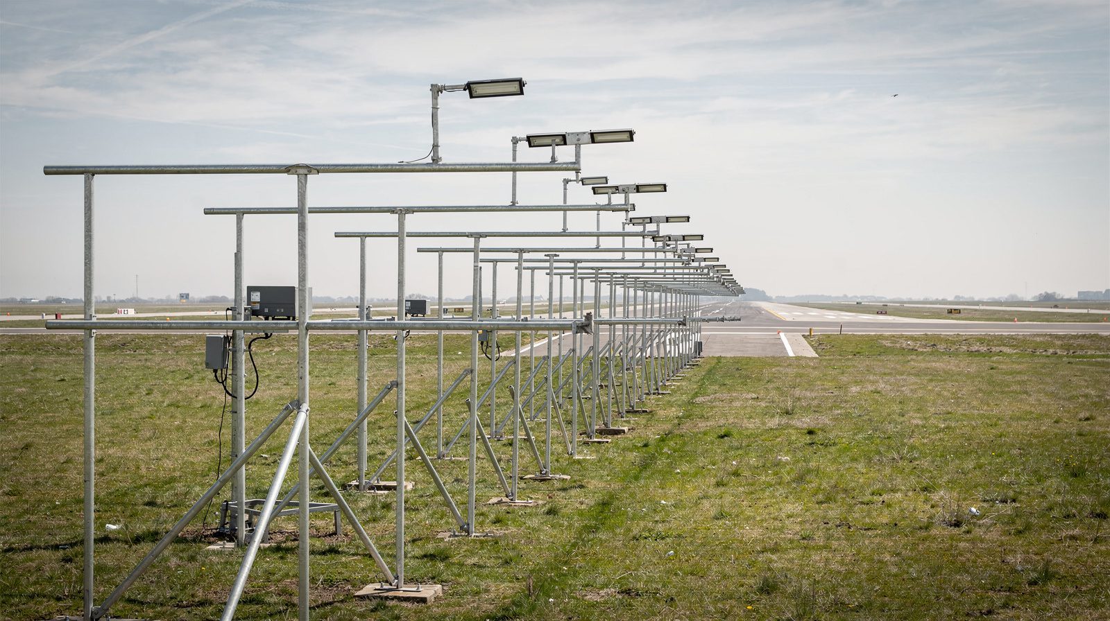
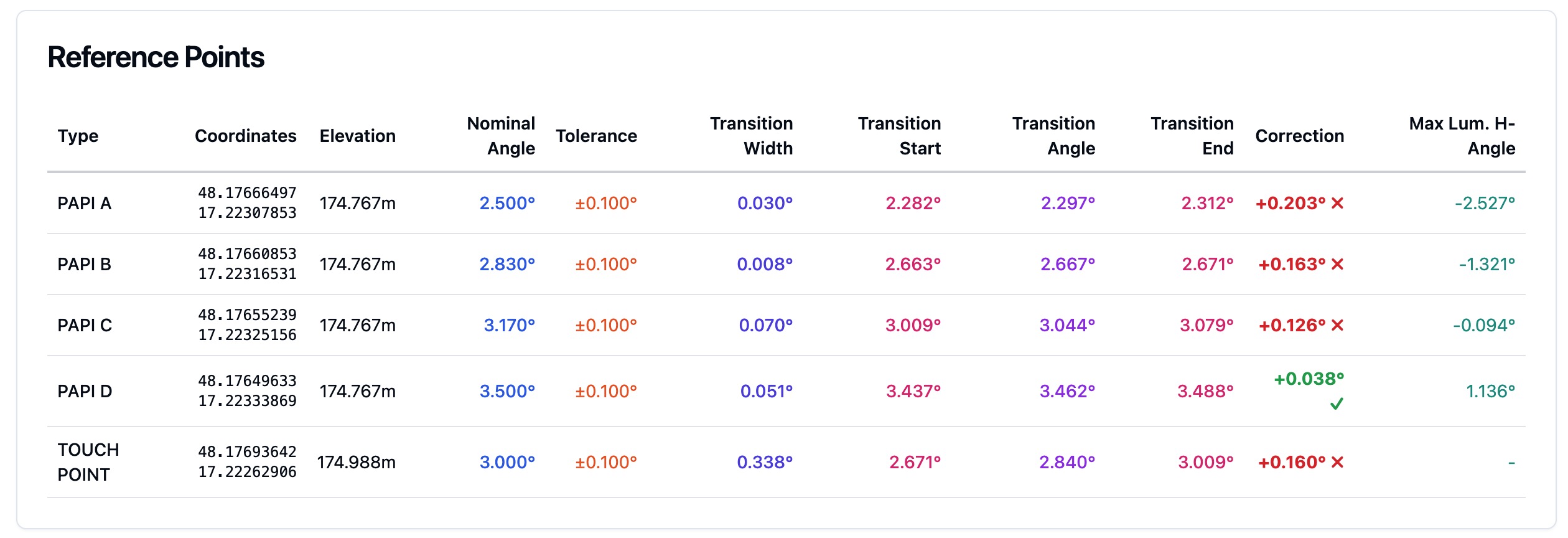
Visual Example
Conclusion
Threshold Crossing Height (TCH) is a foundational concept in modern instrument approach design, ensuring that aircraft of all sizes can safely, efficiently, and consistently land while clearing obstacles and maximizing runway usage. Understanding TCH, and its relationship to aircraft geometry, regulatory standards, and operational procedures, is essential for pilots, engineers, and airport operators worldwide.
Frequently Asked Questions
- What is Threshold Crossing Height (TCH) in aviation?
- TCH is the theoretical height above the runway threshold where an aircraft’s glide slope antenna crosses when maintaining the published ILS or MLS approach path. It is a key design parameter ensuring obstacle clearance, runway safety, and efficient landing operations.
- How is TCH different from Screen Height and Reference Datum Height (RDH)?
- TCH refers to the glide slope antenna’s height above the threshold, while Screen Height is the main landing gear’s height at the runway threshold or end. RDH is a design datum for the glide path, ideally matching TCH but used primarily in approach procedure construction.
- Why is TCH important for approach procedures?
- TCH ensures that aircraft on precision approaches safely clear obstacles near the runway threshold and maximize usable landing distance. It also standardizes approach profiles for different aircraft and supports automated landing systems.
- What are the standard regulatory values for TCH?
- ICAO and FAA standards set the TCH (or RDH) at 15 meters (50 feet) for most precision approaches, with small tolerances for local conditions. Category II/III approaches have stricter requirements, typically 50–60 feet.
- How does aircraft size affect TCH and Wheel Crossing Height (WCH)?
- Large aircraft have glide slope antennas positioned higher and further ahead of the main wheels, resulting in actual wheel crossing heights lower than the TCH. Approach procedures must ensure safe WCH for the largest aircraft expected on the runway.
This is a reference entry. TarmacView provides drone inspection services and doesn't sell the equipment or materials described in this glossary.