ALSF, MALSR or PALS: Choosing an Approach Lighting Configuration
What really decides an approach lighting configuration, why the ICAO and FAA vocabularies do not map onto each other, and what each layout costs to keep serviceable.
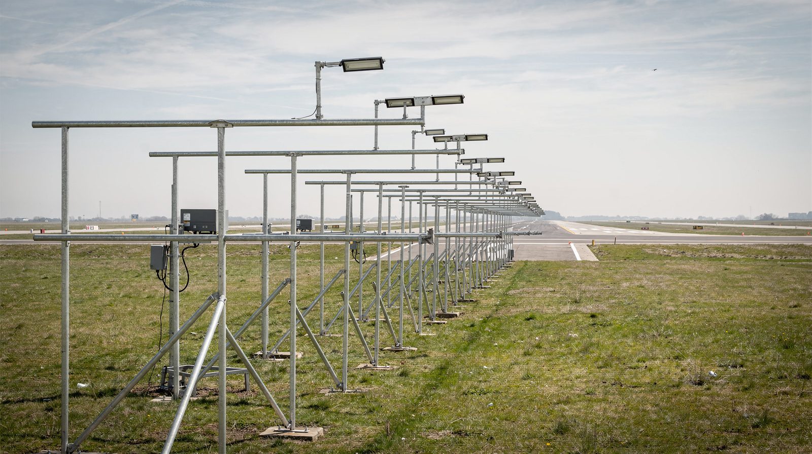 CROSSBARS · HAZE
The choice is mostly made for you
An approach lighting configuration reads like a menu and behaves like a constraint problem. By the time an airport is genuinely choosing, four facts have usually narrowed the answer to one or two layouts, and most of the remaining decision is about what happens after the system is energised rather than what it looks like on the drawing.
The minima you want to publish. This is the largest constraint and the one that drives the capital case. Visibility credit in FAA procedure design is tied to the length of the approach lighting array and to what else the runway has. A system of 1,400 ft or more supports a minimum around 1/2 statute mile, which is 2400 RVR, and touchdown zone plus runway centreline lighting behind a suitable array is what takes a runway down to 1800 RVR. In current FAA practice, an ILS or LPV published below 3/4 mile is backed by one of the four full-length systems, all of which run 2,400 ft from the threshold. A non-precision approach does not need that reach and rarely justifies it.
How much land there is beyond the threshold. ICAO asks for 900 m of centreline for both its precision families and not less than 420 m for the simple one. The FAA full-length systems occupy 2,400 ft, which is 732 m. If the airport boundary, a road or a river arrives at 500 m past the threshold, the ambition is already capped, and the honest options are a shorter configuration or a land acquisition.
What the ground does. Annex 14 asks that the array lie as nearly as practicable in the horizontal plane through the threshold. Falling terrain is answered with stanchions of increasing height, which is why a system on a bluff or an estuary costs several times what the same system costs on a flat field. Rising terrain does the opposite and pushes units into the approach surface . The Annex acknowledges the tall case directly: beyond 300 m from the threshold, where a supporting structure exceeds 12 m, the frangibility requirement applies to the top 12 m only.
Power and people. A full-length array is close to a kilometre of series circuit, one or more constant current regulators, a duct run, and in most installations an access track that has to stay driveable in winter. High-intensity systems draw more, step through more brightness settings and carry more lamps than medium-intensity ones. That difference is invisible in the selection study and very visible in the maintenance budget.
Two vocabularies that do not line up
The confusion in this subject is not technical. It is lexical.
ICAO Annex 14, Volume I, defines three configurations by function: simple, precision category I, and precision categories II and III. It is a performance specification, written in metres, that an installer meets in whatever way suits the site. The FAA instead names products, and the names are what appear on charts and in procurement: ALSF-2, ALSF-1, SSALR, MALSR, MALSF, MALS and ODALS. PALS , precision approach lighting system, is the generic label for the category-supporting end of that list rather than a specific layout you can order.
The two vocabularies overlap but do not convert. ICAO spaces centreline lights at 30 m and simple systems at 60 m. The FAA spaces at 100 ft and 200 ft, which are near neighbours and not equalities. ICAO measures 900 m of steady centreline. The FAA measures 2,400 ft of system, and on several configurations the outer third of that figure is sequenced flashers rather than steady lights. That last difference is where most published comparisons go wrong.
| ICAO Annex 14 family | Defining features | Closest FAA configurations | Where the match breaks |
|---|---|---|---|
| Simple | Centreline not less than 420 m, 60 m spacing, one crossbar at 300 m | MALS, SSALS, ODALS | ODALS is a row of omnidirectional flashers, not a steady centreline at all |
| Precision CAT I | 900 m centreline, 30 m spacing, crossbar at 300 m, further crossbars at 150, 450, 600 and 750 m on single-light variants | MALSR, SSALR | FAA length is 2,400 ft, not 900 m, and on MALSR and SSALR the outer 1,000 ft is flashers |
| Precision CAT II and III | 900 m centreline, crossbars at 150 m and 300 m, red side row barrettes to 270 m from threshold | ALSF-2 | ALSF-2 is the only close fit, and the inner geometry is arranged to FAA distances |
The practical consequence is that “MALSR is the CAT I system” is a useful shorthand and a false dimensional statement. It supports CAT I operations. It is not a 900 m ICAO CAT I array, and an authority working to Annex 14 will not accept it as one without a site specific assessment.
What a sequenced flashing row buys
Sequenced flashers are the cheapest length an approach array can buy.
Annex 14 is precise about the behaviour. Each flashing light fires twice a second in sequence, starting at the outermost unit and progressing toward the threshold. The eye picks up the direction of travel before it resolves anything else in the array, which is why crews report acquiring the flashers first in haze and low cloud and the steady pattern second.
The FAA turns that property into a length strategy. On a MALSR the steady barrettes stop at 1,400 ft from the threshold. The runway alignment indicator lights, five high-intensity flashers at 200 ft spacing, carry the system from 1,600 ft out to 2,400 ft. Five units deliver a thousand feet of additional reach that would otherwise take five more barrettes of five lamps each. That is the trade in one sentence: flashers are cheap per foot of reach and highly visible in poor air, and they contribute nothing to roll reference, because a moving point of light is not a horizon. Systems that need roll cues near the threshold buy them with crossbars and side rows instead.
The configurations, side by side
| Configuration | Length from threshold | Steady pattern | Flashers | Supports | Land and structure demand |
|---|---|---|---|---|---|
| ALSF-2 | 2,400 ft | Centreline barrettes at 100 ft, crossbars at 500 ft and 1,000 ft, red side rows over the inner 900 ft | 15, outer segment | CAT II and CAT III precision approach | Highest. Full 732 m corridor, heaviest cable and duct run |
| ALSF-1 | Not given in the current FAA order | Older configuration, drawn in the FAA AIM with centreline barrettes, a 1,000 ft crossbar and red bars near the threshold, no side rows | Yes, per the AIM drawing | Not stated in Order JO 6850.2C | As ALSF-2 without the side rows |
| SSALR | 2,400 ft | Simplified short array in the inner 1,400 ft | 5 RAIL, 1,600 to 2,400 ft | CAT I | Full corridor, but sparse outer half |
| MALSR | 2,400 ft | 9 bars of 5 white lamps: 7 on the centreline to 1,400 ft and 2 forming a crossbar at 1,000 ft | 5 RAIL, 1,600 to 2,400 ft | CAT I, down to 1800 RVR with TDZ and centreline lights | Full corridor, medium-intensity plant |
| MALSF | 1,400 ft | Same steady bars as MALS | 3, on the outer bars | Non-precision, night identification | 427 m corridor |
| MALS | 1,400 ft | 9 bars of 5 white lamps | None | Non-precision and visual | 427 m corridor |
| ODALS | About 1,500 ft | None | 7 omnidirectional flashers | Non-precision, poor visual environment | Lowest. No continuous array to maintain |
Two entries in that table deserve reading twice. MALS and MALSR share an identical inner 1,400 ft, so the entire difference between a non-precision aid and a CAT I aid is five flashers and the 1,000 ft of corridor they occupy. And ODALS is not a short ALS . It is a different idea, a line of flashers that tells a crew where the runway is without ever telling them how level they are.
What each one costs you once it is switched on
This is the part the selection studies leave out, and it is the part an operations budget lives with for thirty years.
Start with unit count, because almost everything downstream scales with it. A MALSR is nine bars of five lamps plus five flashers, so about fifty units in total. An ALSF in the CAT II and III layout runs to roughly 250 steady lamps plus its 15 flashers, once the threshold bar, the centreline barrettes, the crossbars and the side row barrettes are counted. That is a factor of five in lamps, in spare stock, in connectors, in isolating transformers and in the time any full check takes.
| Burden | Medium-intensity, 1,400 ft (MALS class) | Medium-intensity, 2,400 ft (MALSR class) | High-intensity, 2,400 ft (ALSF class) |
|---|---|---|---|
| Approximate light units | 45 | 50 | 250 or more |
| Circuit length beyond the fence | About 430 m | About 730 m | About 730 m, more circuits |
| Land access negotiated off airport | Sometimes | Usually | Usually |
| Serviceability objective under Annex 14 | Per the applicable category | 85% for CAT I | 95% inner 450 m, 85% beyond, for CAT II and III |
| Adjacent failures tolerated | Restricted | Restricted | Restricted, with a narrow barrette and crossbar exception |
| Colour to verify | White only | White only | White plus red side rows |
| Failure that hurts most | A dead outer bar | A flasher out of sequence | A gap that changes the pattern near the threshold |
Three of those rows carry the real cost. Colour is one, because a red side row that has drifted toward orange is a defect that no lamp-out count will find. Adjacency is another, because the standard cares where the failures sit and not only how many there are, so a 95% pass can still be a failed array if the missing 5% is contiguous. And the flashing row is the third, because sequence direction is a system-level property that survives every component-level test. A row that fires outward is worse than a row that does not fire at all, and it will pass a continuity check every time.
There is also the case where none of the standard configurations fit, either because the land is not available or because the installation is temporary. Modular and rapidly deployable arrays such as E-ALS exist for exactly that gap. They change the deployment economics substantially and they do not change what the crew needs to see, which means they inherit the same verification obligations.
Choosing, in practice
Work it in this order. Establish the lowest minima the runway can realistically support given its navigation aid, its runway lighting and its obstacle environment. Measure the land you actually control past the threshold, and the land you could reach an agreement over. Survey the ground profile, because stanchion heights and access tracks are usually the largest single line in an approach lighting project. Only then pick a configuration, and price the thirty-year upkeep alongside the install, because on a high-intensity array the upkeep is the larger number.
The last step is the one operators most often defer. A configuration is a commitment to keep a specific geometric pattern serviceable in a place that is inconvenient to reach, and the array that is cheapest to install is not always the one that is cheapest to prove. We fly that verification as part of an approach lights inspection , and the same logic that makes a whole-airfield visit cheaper than three partial ones applies here too, which is the argument we set out in what a PAPI inspection actually costs .
The short version
Minima and available land decide the configuration. Terrain decides what it costs to build. Lamp count, colour and pattern geometry decide what it costs to keep. The ICAO and FAA names describe the same job in incompatible units, so treat any cross-walk between them as approximate and check the actual drawing. And remember that on the FAA side the headline 2,400 ft is a system length, not a length of steady lights, which on a MALSR stop at 1,400 ft and hand the rest of the job to five flashers.
Founded by flight-inspection veterans who spent decades measuring PAPI lights for aviation authorities across Europe.
Learn more
Related terms
03 TERMSApproach Lighting System: ALS Configurations and Specs
Approach lighting systems explained: ICAO simple, CAT I and CAT II/III patterns, FAA ALSF-2, MALSR and SSALR, and the lengths, spacings and tolerances.
Approach Lighting System (ALS)
A comprehensive overview of Approach Lighting Systems (ALS): definitions, purposes, configurations, technical standards, operational context, and their impact on aviation safety. ALS are critical visual aids installed along runways to enhance pilot guidance during approach and landing, especially in low-visibility conditions.
Precision Approach Lighting System (PALS)
A Precision Approach Lighting System (PALS) is a specialized runway lighting system providing critical visual cues to pilots during the final phase of instrument approaches, ensuring safe landings in low visibility and at night.
Further reading
03 ARTICLES
Approach Lighting System Inspection
What an approach lighting system does for the crew, what Annex 14 asks of it in service, and why 900 metres of array off the airport is hard to…

Runway Edge Light Inspection: What ICAO Requires and How It Is Measured
What ICAO Annex 14 requires of runway edge lights, what it leaves open, and how intensity, colour and coverage are actually measured in the field.
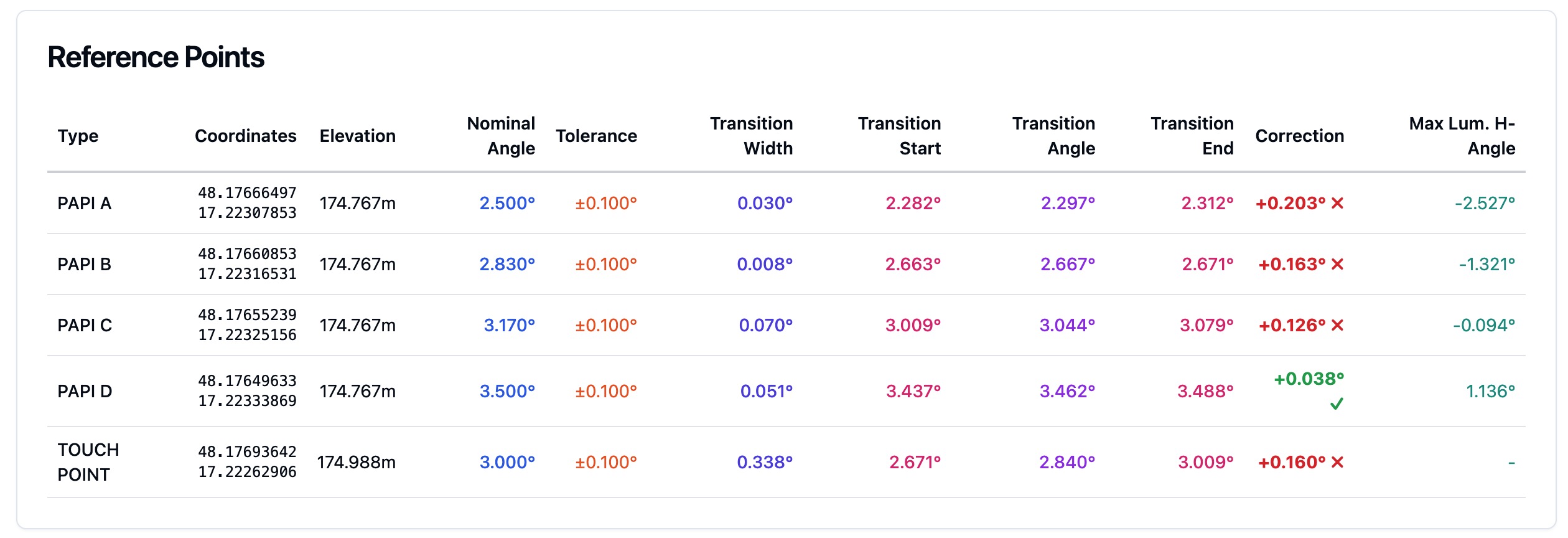
What ICAO Annex 14 Actually Requires of Your PAPI
The tolerances behind a PAPI protocol, what an authority looks for in the evidence, and how often the system has to be verified to stay certifiable.