Approach Lighting System Inspection
What an approach lighting system does for the crew, what Annex 14 asks of it in service, and why 900 metres of array off the airport is hard to inspect.
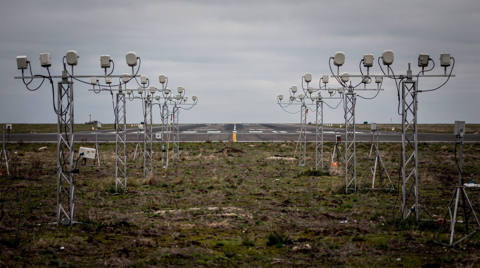 APPROACH BARS · OVERCAST
What the crew is actually reading
An approach lighting system is the bridge between two different kinds of flying. Until the crew breaks out, the aircraft is being flown on instruments down a defined approach path . After it breaks out, the aircraft is being flown by eye. The lights are what makes that handover survivable in weather where there is nothing else to look at.
What the lights supply in the seconds around the transition is not just “the runway is that way”. A row of centre line lights running away from the threshold gives distance and alignment. The crossbars, set at right angles to that row, give a horizon reference and a sense of roll. The sequenced flashers, where fitted, give a direction of travel that the eye picks up before it resolves anything else. Take the crossbars away and the crew has alignment but a much poorer read on bank angle. Take the length away and they have alignment but less time.
This is why the system is inspected as a pattern rather than as a collection of lamps. A precision approach is flown to a decision point, and at that point the crew either has enough of the pattern to continue or it does not. A system with the right total number of working lights but a hole in the wrong place has failed even though the count looks fine.
The three families Annex 14 defines
Annex 14 , Volume I, Chapter 5, defines three approach lighting configurations. They differ in reach, in what they add beyond a centre line, and in the operations they are meant to support.
| Attribute | Simple | Precision CAT I | Precision CAT II and III |
|---|---|---|---|
| Centre line length from threshold | Not less than 420 m, whenever possible | 900 m, wherever possible | 900 m, wherever possible |
| Centre line spacing | 60 m | 30 m, innermost light 30 m from threshold | 30 m, innermost light 30 m from threshold |
| Crossbars | One, 18 m or 30 m long, at 300 m | One 30 m crossbar at 300 m, plus crossbars at 150, 450, 600 and 750 m where the centre line is single lights | Two, at 150 m and 300 m, plus 450, 600 and 750 m in some centre line variants |
| Side rows | None | None | Two, red barrettes, extending 270 m from threshold, or 240 m where the serviceability objective is demonstrated |
| Centre line colour | Chosen so the system is distinguishable from other aeronautical ground lights and from extraneous lighting | Variable white | Variable white |
| Sequenced flashers | Optional aid where night identification is difficult | Recommended where the centre line consists of barrettes | Recommended beyond 300 m where the centre line consists of barrettes |
Where flashers are fitted, Annex 14 is specific about how they run. Each flashing light is flashed twice a second in sequence, starting at the outermost light and progressing toward the threshold. Direction matters as much as rate. A row that fires the wrong way is worse than a row that does not fire at all.
The FAA names its systems differently, which is where ALSF , MALSR and the general PALS label come from. The underlying job is the same, and so is most of the inspection. Choosing between those configurations for a given runway is a separate question, and we have written it up separately.
What Annex 14 asks once the system is in service
Design conformity is a one-off question. Serviceability is the recurring one, and this is where the standard becomes a measurable target rather than a drawing.
For a CAT II or III runway, the preventive maintenance system has to have as its objective that all approach and runway lights are serviceable during operations, and in any event that the following minima hold. For a CAT I runway the objective is a single flatter figure. The comparison is instructive.
| Element | CAT I objective | CAT II and III objective |
|---|---|---|
| Approach lighting system, inner 450 m | 85% of the system | 95% |
| Approach lighting system beyond 450 m | 85% of the system | 85% |
| Runway centre line lights | Not specified under this objective | 95% |
| Runway threshold lights | 85% | 95% |
| Runway edge lights | 85% | 95% |
| Touchdown zone lights | Not specified under this objective | 90% |
| Runway end lights | 85% | 75% |
| Adjacent unserviceable lights | Not permitted unless the spacing is significantly less than specified | Not permitted, except that two adjacent may be permitted in a barrette or a crossbar |
Two things in that table are easy to miss. The first is the split at 450 m, which says plainly that the inner half of a CAT II or III array carries more weight than the outer half. The second is the adjacency rule, and the accompanying requirement that the allowable percentage of unserviceable lights must not be permitted in a way that alters the basic pattern. Those two clauses are why a purely statistical serviceability report is not enough. You have to know which units are out and where they sit.
Annex 14 also recommends what the checks contain. For a CAT II or III runway the preventive maintenance system should include visual inspection and in-field measurement of the intensity, beam spread and orientation of the approach and runway lights, control and measurement of the electrical characteristics of each circuit, and confirmation that the intensity settings used by air traffic control actually do what they are commanded to do. The measurement should cover all lights as far as practicable, should use a mobile measuring unit accurate enough to analyse individual lights, and should be repeated at a frequency driven by traffic density, local pollution, equipment reliability and the trend in previous results, but in any event not less than twice a year for in-pavement lights and not less than once a year for the others.
There is also a uniformity constraint that catches installations nobody would otherwise question. Within the ellipse defining the main beam, the maximum intensity must not be more than three times the minimum. A system where every unit passes its own minimum but the array is visibly patchy across the beam is out of specification.
Why an approach array is harder than an edge light row
A runway edge light row lives inside the fence, on flat ground, at a known height, next to a paved surface you can drive. Almost none of that is true of an approach array.
It is long, and most of it is not on the airport. A CAT I or CAT II/III system reaches 900 m out from the threshold. That distance crosses boundary fences, perimeter roads, drainage, farmland, and in coastal installations open water. Access is negotiated rather than assumed.
The ground does not cooperate. Annex 14 asks that the system lie as nearly as practicable in the horizontal plane passing through the threshold. Where the terrain falls away, that plane is held by putting the lights on stanchions of increasing height. The result is an array whose units sit at a dozen different elevations, none of them convenient. Frangibility requirements acknowledge this directly: beyond 300 m from the threshold, where a supporting structure exceeds 12 m in height, the frangibility requirement applies to the top 12 m only. Structures that tall are not inspected from a ladder in a maintenance window.
Screening is a real failure mode. The standard requires that no light other than one in the central part of a crossbar or a centre line barrette be screened from an approaching aircraft, and that no object other than an ILS or MLS azimuth antenna protrude through the plane of the approach lights within 60 m of the centre line. Vegetation grows. Equipment gets installed. A unit that is electrically perfect and optically invisible from the approach surface is still a defect, and it is one that only shows up when you look from where the crew looks.
The right viewpoint is airborne. All of the above is why we fly the array rather than walking it. One descent on the nominal glide path sees the pattern the way it is designed to be seen, and a hover off the outer end is where a dimming step can be watched settle and a flashing row can be counted. The same argument applies to a PAPI, and we have written up what Annex 14 requires of that system in more detail.
What degrades, and how it shows
Lamp failures are the obvious one and the least interesting. They are visible, countable and easy to fix. The problems that matter are the ones that pass a walk-round.
Aiming drift is first. A stanchion-mounted unit is a lever arm in the wind, and mounting hardware loosens. The unit still lights, still shows the right colour, and no longer puts its main beam where the crew is. Ground settlement under a foundation does the same thing more slowly.
Intensity mismatch is second. Lamps age at different rates, optics craze, and lens surfaces accumulate a film that nobody notices because it happens to every unit at once. The array stays legible in clear air and loses its build-up toward the threshold in the weather it exists for.
Colour drift is third, and it is confined to the systems that use colour. Red side row barrettes that have shifted toward orange are still obviously red on the ground and ambiguous at range. Annex 14 also asks that the intensity of the red lights be compatible with the intensity of the white, so a side row can be out of specification purely by being too dim relative to its neighbours.
Then there are the pattern faults: a crossbar with a gap that has grown past what the standard allows, a flashing row that has lost its sequence direction after a controller replacement, a dimming step that some units follow and others do not, and lights near the approach that a crew could mistake for part of the system. None of these is a lamp failure. All of them change what a visual approach or a break-out at minima actually looks like.
What a finished inspection should hand over
A serviceability count is not an inspection report. What an authority can act on is a per-unit record: every unit in the array identified by its position in the pattern, the colour it is meant to show and the colour it showed, its measured intensity and beam behaviour, and its status as serviceable, unserviceable or deliberately out of service. On top of that, the pattern-level findings that the per-unit table cannot express, which are the adjacency and continuity checks, the crossbar geometry, the dimming steps stepped through together, the flashing row timed and its direction confirmed, and the screening and misleading-lights observations from the approach itself.
Then the evidence. Photo and video from the flown descent, tied to the units they show and to a specific flight on a specific day, so that a reviewer can see the array rather than take the numbers on trust. And for anything out of tolerance, the correction, because a report that says a unit fails tells your team there is a problem and a report that says by how much tells them what to turn.
That is the shape of the deliverable on our approach lights inspection , and it is the same shape whether your report goes to ICAO, EASA or FAA. The letterhead changes. The array does not.
The short version
An ALS is a pattern, judged from the air, against a standard that cares where the failures are and not only how many there are. Its inner 450 m is held to a higher bar than its outer half on a CAT II or III runway. Its measurement is supposed to cover intensity, beam spread and orientation on every light that can practicably be measured, at least annually. And most of it sits outside the fence on structures nobody wants to climb. That combination is exactly the case for measuring it from the approach rather than from the ground.
Founded by flight-inspection veterans who spent decades measuring PAPI lights for aviation authorities across Europe.
Learn more
Related terms
03 TERMSApproach Lighting System (ALS)
A comprehensive overview of Approach Lighting Systems (ALS): definitions, purposes, configurations, technical standards, operational context, and their impact on aviation safety. ALS are critical visual aids installed along runways to enhance pilot guidance during approach and landing, especially in low-visibility conditions.
Approach Lighting System: ALS Configurations and Specs
Approach lighting systems explained: ICAO simple, CAT I and CAT II/III patterns, FAA ALSF-2, MALSR and SSALR, and the lengths, spacings and tolerances.
Lighting Control in Airport Operations
Lighting control at airports involves advanced systems for managing runway, taxiway, and approach lights, ensuring safe and efficient aircraft movements. It covers intensity settings, automation, reliability, environmental impact, and regulatory compliance.
Further reading
03 ARTICLES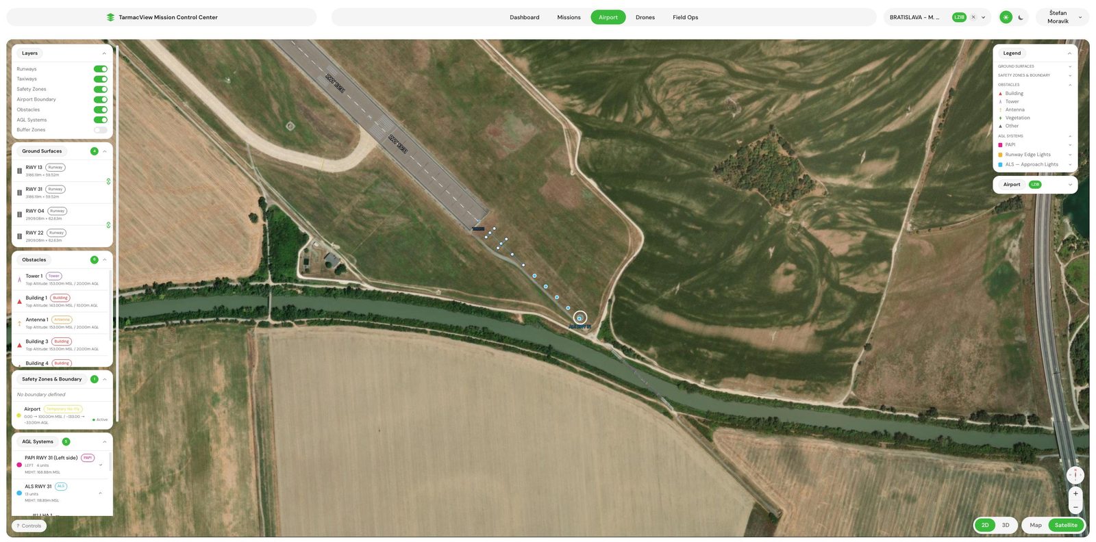
Approach Lighting System Inspection by Drone
Drone approach lighting system inspection from the pilot's eye view. Pattern, colour, intensity, coverage and the flashing row verified unit by unit,…
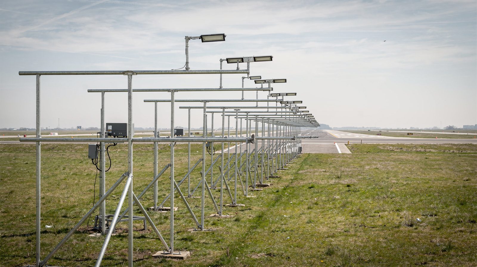
ALSF, MALSR or PALS: Choosing an Approach Lighting Configuration
What really decides an approach lighting configuration, why the ICAO and FAA vocabularies do not map onto each other, and what each layout costs to…

Runway Edge Light Inspection: What ICAO Requires and How It Is Measured
What ICAO Annex 14 requires of runway edge lights, what it leaves open, and how intensity, colour and coverage are actually measured in the field.