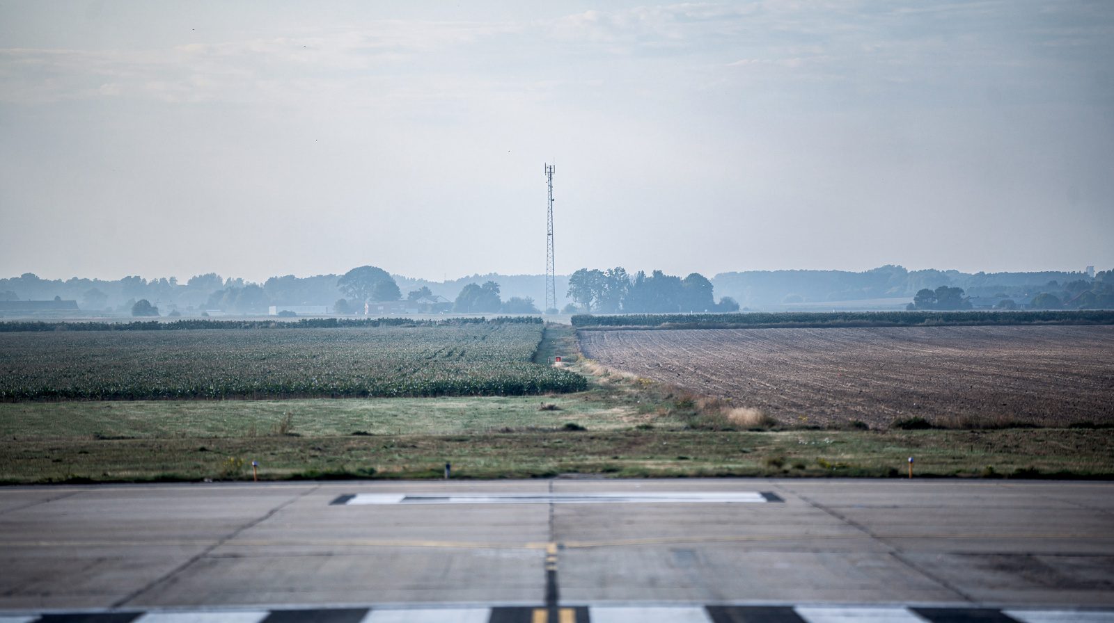
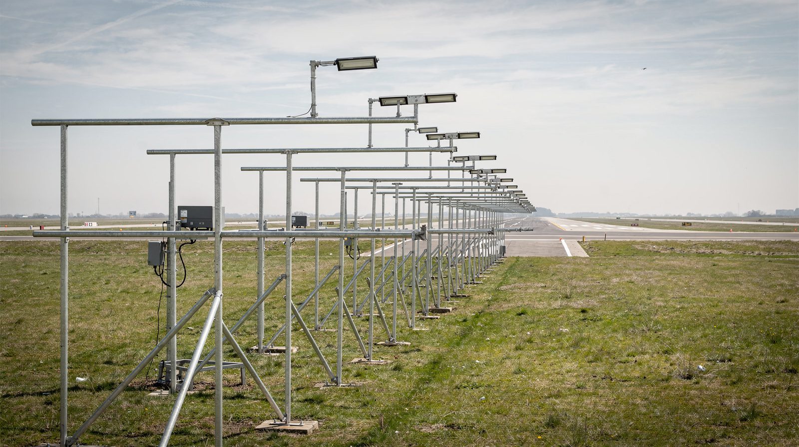
What is an approach surface?
Approach Surface
Approach surfaces are among the most fundamental concepts in airport planning and aviation safety. They are imaginary, three-dimensional surfaces, established by regulation, that extend outward and upward from the ends of runways to protect the navigable airspace necessary for safe aircraft approach and landing operations. Understanding, establishing, and maintaining clear approach surfaces is essential for airport operators, planners, and regulatory authorities worldwide.
Table of Contents
- Definition
- Regulatory Context
- Technical Definition and Geometry
- Distinction from Related Surfaces
- Applicability and Intent
- Types of Approach Surfaces
- Establishment and Evaluation Process
- Operational and Planning Impact
- Examples and Use Cases
- Implementation in Airport Planning and Design
- Related Terms
- References and Further Reading
- Summary Table: Approach Surface Parameters
- Key Takeaways
Definition
An approach surface is a three-dimensional, sloped imaginary plane extending outward and upward from the end of a runway, centered on the extended runway centerline. It is not a physical structure, but a regulatory boundary that protects the critical airspace necessary for safe landing and instrument approach operations. The geometry (slope, width, length) of this surface is determined by the type of approach the runway supports, visual, non-precision, or precision.
Approach surfaces are codified in aviation regulations such as 14 CFR §77.19 , FAA AC 150/5300-13A , and ICAO Annex 14 for international standards.
Regulatory Context
Approach surfaces are mandated by a comprehensive framework of federal and international regulations to ensure uniform protection of airspace at all certified and public-use airports.
- 14 CFR Part 77: Defines imaginary surfaces, including approach surfaces, and sets out the requirements for notification and evaluation of proposed construction or alteration near airports.
- FAA AC 150/5300-13A: Provides detailed geometric criteria for approach and other airport surfaces for all categories of runways.
- ICAO Annex 14: Internationally, Obstacle Limitation Surfaces (OLS), including the approach surface, are defined to standardize airport protection globally.
- State & Local Laws: Some U.S. states and municipalities have additional or more restrictive requirements.
Key references:
Technical Definition and Geometry
General Characteristics
- Origin: Begins at the end (threshold) of the primary surface of a runway.
- Orientation: Centered along the extended runway centerline.
- Shape: Expands outward and upward, forming a wedge or trapezoidal shape.
- Slope, Width, Length: Determined by the type of approach (visual, non-precision, precision).
Geometric Parameters
| Runway/Approach Type | Inner Width (ft) | Outer Width (ft) | Length (ft) | Slope (H:V) |
|---|---|---|---|---|
| Visual, Utility | 250 | 1,250 | 5,000 | 20:1 |
| Visual, Other | 500 | 1,500 | 5,000 | 20:1 |
| Non-Precision, Utility | 500 | 2,000 | 5,000 | 20:1 |
| Non-Precision, Other | 500/1,000 | 3,500/4,000 | 10,000 | 34:1 |
| Precision | 1,000 | 16,000 | 10,000 + 40,000 | 50:1/40:1 |
ICAO Example:
Precision approach runway CAT I:
- Inner edge: 300 m (984 ft)
- Outer edge: 1,200 m (3,937 ft)
- Length: 3,000 m (9,843 ft)
- Slope: 2%
See FAA AC 150/5300-13A Table 3-2 and ICAO Annex 14 Table 4-1 .
Distinction from Related Surfaces
| Surface Type | Function | Relation to Approach Surface |
|---|---|---|
| Primary Surface | Rectangular area along runway. | Approach surface begins at its end. |
| Departure Surface | Outward/upward from runway departure end. | For departing aircraft (not Part 77). |
| Transitional Surface | Outward/upward at right angles to runway centerline. | Connects approach to horizontal. |
| Horizontal Surface | Flat plane above airport reference point. | Overlays approach surface. |
| Conical Surface | Slopes up from edge of horizontal surface. | Transitions to open airspace. |
ICAO’s OLS system uses similar, though sometimes differently named, surfaces.
Applicability and Intent
Where and When Applied
- All public-use airports: Every runway end, regardless of size or traffic.
- Airport planning, construction, and modifications: Surfaces are defined for existing, planned, or under-construction runways.
- Structure evaluations: Any proposed structure or natural growth within the surface must be evaluated.
- Instrument procedures: Required for development and maintenance of instrument approaches.
Intent
- Obstacle clearance: Ensures a safe, obstacle-free approach path.
- Preservation of airspace: Prevents encroachment into critical approach corridors.
- Support for instrument procedures: Enables lowest possible minima.
- Regulatory compliance: Required for airport certification and funding.
Types of Approach Surfaces
Visual Runway Approach Surface
- For: Runways without instrument approaches (VFR only).
- Slope: 20:1
- Length: 5,000 ft
- Width: 250–500 ft (inner), 1,250–1,500 ft (outer)
Non-Precision Instrument Runway Approach Surface
- For: Runways with lateral guidance only (e.g., VOR, RNAV).
- Slope: 20:1 (utility), 34:1 (other)
- Length: 5,000–10,000 ft
- Width: 500–1,000 ft (inner), 2,000–4,000 ft (outer)
Precision Instrument Runway Approach Surface
- For: Runways with both lateral and vertical guidance (ILS, PAR).
- Slope: 50:1 (first 10,000 ft), 40:1 (next 40,000 ft)
- Length: 10,000 ft + 40,000 ft
- Width: 1,000 ft (inner), 16,000 ft (outer)
Establishment and Evaluation Process
Data Collection:
- Runway coordinates, elevation, approach type.
Surface Definition:
- Calculate surface geometry using regulatory standards.
Surface Generation:
- Use GIS or specialized tools for visualization.
Obstruction Identification:
- Survey existing and proposed objects within the surface.
Obstacle Mitigation:
- Possible actions: removal, marking, lighting, or adjusting approach procedures.
Operational and Planning Impact
Obstruction Penetrations:
Any penetration requires evaluation, may result in restrictions, higher minima, or loss of instrument procedures.Regulatory and Funding Implications:
Compliance with approach surface standards is often a prerequisite for airport certification, grant funding, and ongoing operational authority.
Examples and Use Cases
General Aviation Airport:
Protects low-traffic runways from cell towers or tree growth.Commercial Hub:
Ensures skyscraper construction in the city approaches does not infringe protected airspace.Military Airbase:
Maintains strict obstacle-free corridors for rapid, low-visibility operations.
Implementation in Airport Planning and Design
Airport Layout Plans (ALP):
Approach surfaces are depicted and analyzed in all ALPs for current and future runways.Master Planning:
Long-term development must account for approach surface protection.Community Engagement:
Local zoning and land use policies should support surface preservation.
Related Terms
- Obstacle Limitation Surfaces (OLS) (ICAO)
- Obstruction Identification Surface
- Primary Surface
- Departure Surface
- Transitional Surface
- Horizontal Surface
- Conical Surface
- Instrument Approach Procedure (IAP)
- Runway Protection Zone (RPZ)
- Minimum Descent Altitude (MDA)
- Decision Altitude (DA)
References and Further Reading
- 14 CFR Part 77 – Safe, Efficient Use, and Preservation of the Navigable Airspace
- FAA AC 150/5300-13A – Airport Design
- ICAO Annex 14, Volume I
- FAA Order 8260.3 – United States Standard for Terminal Instrument Procedures (TERPS)
- FAA Approach and Departure Surface Protection Policy
Summary Table: Approach Surface Parameters
| Approach Type | Inner Width | Outer Width | Length | Slope |
|---|---|---|---|---|
| Visual, Utility | 250 ft | 1,250 ft | 5,000 ft | 20:1 |
| Visual, Other | 500 ft | 1,500 ft | 5,000 ft | 20:1 |
| Non-Precision, Utility | 500 ft | 2,000 ft | 5,000 ft | 20:1 |
| Non-Precision, Other | 1,000 ft | 4,000 ft | 10,000 ft | 34:1 |
| Precision | 1,000 ft | 16,000 ft | 10,000+40,000 | 50:1/40:1 |
Key Takeaways
- Approach surfaces are essential for safe aircraft operations and are legally required for every public-use runway.
- Their geometry depends on the most precise approach procedure for each runway end and is detailed in FAA and ICAO standards.
- Protection of these surfaces is critical for airport certification, funding, and the preservation of instrument approach procedures.
- Obstructions must be identified and mitigated to avoid operational restrictions or loss of approach capabilities.
- Approach surfaces should be proactively incorporated into airport master planning, community zoning, and infrastructure development.
Frequently Asked Questions
- Why are approach surfaces necessary?
- Approach surfaces are crucial to maintaining obstacle-free airspace for aircraft on final approach. They help prevent the construction or growth of obstructions that could compromise the safety of landings and support regulatory compliance for airport certification and funding.
- What happens if an object penetrates the approach surface?
- Any penetration is classified as an obstruction. The FAA or relevant authority will evaluate the risk, and mitigation may be required, ranging from lighting and marking to reduction in approach minima or even removal of the obstruction.
- Are approach surfaces the same worldwide?
- While the concept is universal, dimensions and terminology may vary. In the United States, approach surfaces are defined in 14 CFR Part 77 and FAA AC 150/5300-13A, while internationally, ICAO Annex 14 defines similar Obstacle Limitation Surfaces (OLS).
- How can I find the exact approach surface dimensions for my airport?
- Refer to your airport's layout plan, FAA AC 150/5300-13A, or consult with airport planning professionals. The required dimensions depend on runway use, approach type, and regulatory framework.
- Do approach surfaces apply to private airports?
- While federal regulations focus on public-use airports, many states and municipalities extend approach surface requirements to private-use airports, especially those supporting instrument procedures or commercial activity.
This is a reference entry. TarmacView provides drone inspection services and doesn't sell the equipment or materials described in this glossary.