Obstacle Limitation Surfaces: Surveying the Approach
What obstacle limitation surfaces are, which ones matter at a regional aerodrome, and how the approach gets surveyed to prove nothing has grown into it.
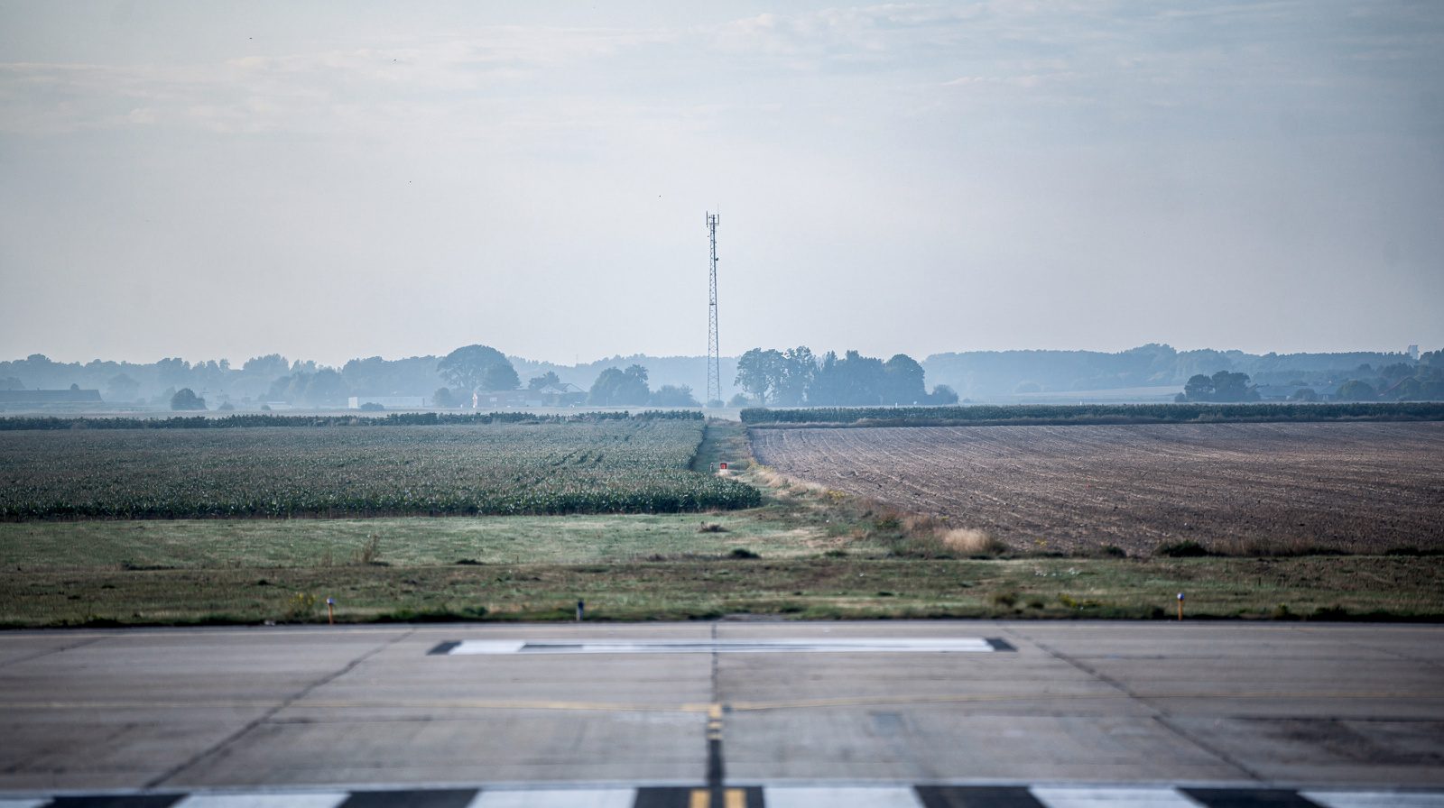 APPROACH · MAST ON HORIZON
One name, a whole family of surfaces
The phrase sounds like a single sloping plane over the runway end. It is not. Obstacle limitation surfaces are a family of imaginary surfaces wrapped around an aerodrome, and an airfield can be perfectly clear on one of them while being penetrated on another.
There is more than one surface because an aeroplane near an airfield is doing more than one thing. It descends on final, it climbs out, it turns after departure, and sometimes it abandons a landing at low height and goes around. Each manoeuvre puts the aircraft in a different volume of air, and each volume needs its own protection. A single surface tuned to the descent would leave the go-around unguarded, and one generous enough to cover everything would sterilise more land than any community would accept.
So the standard splits the problem. Annex 14 , Volume I is the source document, and Amendment 18 to it restructures the whole set into two categories that behave very differently. Obstacle Free Surfaces are exactly what the name says: nothing is permitted through them, full stop. Obstacle Evaluation Surfaces are looser. A penetration there is not automatically forbidden, but it has to be studied, justified and recorded rather than ignored.
That distinction is the most useful thing an operator can hold in their head. It tells you which findings stop operations and which start paperwork.
The timing catches people out. Amendment 18 was adopted in 2025 and does not enter into effect until November 2030. The code-number tables most operators know are still in force, and the new geometry is the one to plan against. Nobody has to switch today, but nobody sensible plants a windbreak against the old numbers.
The amendment also changes how the surfaces are sized. The older tables key off the aerodrome reference code number. The new ones key off the Aeroplane Design Group, which classifies aircraft by indicated airspeed at threshold and by wingspan together. Group I is under 169 km/h with a wingspan below 24 m. Group III covers 36 m up to but not including 52 m of span. A field whose critical aeroplane is a narrowbody under 36 m of span sits in group II, and which sub-group depends on threshold speed rather than on the runway.
Which surfaces actually bite at a regional aerodrome
Most of the family never causes anyone a problem. The horizontal surface sits high and wide, the conical geometry is a planning concern rather than an inspection one, and the transitional surfaces along the strip were settled the day the aerodrome was built. Three things generate almost all the real findings.
The first is the approach surface , the wedge rising along the extended centre line from a line 60 m out from the threshold. It is closest to the ground where aircraft are lowest and slowest, and it is the surface that vegetation and construction reach first.
The second is the take-off climb surface at the other end of the same runway, which matters most in an engine-out scenario that nobody wants to test.
The third is the evaluation surface for the instrument procedure, if the runway has one. That is the surface that quietly determines your minima.
Here is what the approach surface looks like under the Amendment 18 tables, comparing a non-instrument runway with an instrument one for the same aircraft group.
| Aeroplane design group | Runway type | Distance from threshold | Inner edge | Divergence each side | Length | Slope |
|---|---|---|---|---|---|---|
| I | Non-instrument | 30 m | 60 m | 10% | 1 600 m | 5% |
| I | Instrument | 60 m | 110 m | 10% | 4 500 m | 3.33% |
| IIC | Non-instrument | 60 m | 100 m | 10% | 2 500 m | 3.33% |
| IIC | Instrument | 60 m | 155 m | 10% | 4 500 m | 3.33% |
| III | Non-instrument | 60 m | 125 m | 10% | 2 500 m | 3.33% |
| III | Instrument | 60 m | 175 m | 10% | 4 500 m | 3.33% |
Two things fall out of that table. Adding an instrument procedure does not just change the charts, it nearly doubles the length of protected ground and widens the inner edge by half. And the smallest aircraft group on a visual runway gets the steepest surface, 5%, because a light aeroplane on a short final can out-climb terrain a jet cannot.
Where a runway carries a precision approach, a second and much larger surface is laid over the first for evaluation. Its geometry is the same for every aircraft group, which surprises people.
| Component | Section | Distance from threshold | Inner edge | Length | Divergence each side | Slope |
|---|---|---|---|---|---|---|
| Approach | 1st | 60 m | 300 m | 3 000 m | 15% | 2% |
| Approach | 2nd | 9 600 m | 15% | 2.5% | ||
| Missed approach | 1st | 900 m | 300 m | 1 800 m | 17.48% | 2.5% |
| Missed approach | 2nd | 10 200 m | 25% | 2.5% | ||
| Transitional | 14.3% |
More than twelve kilometres of protected approach, spreading at 15% either side, is a very large piece of countryside, and it is the piece a growing town expands into. That geometry is the one our own approach obstacle clearance check is built on.
The problem is change, not design
Aerodromes are almost never built with a penetrating obstacle. The surfaces are drawn before the concrete is poured, the land is bought or the easements are written, and on opening day the approach is clean.
Then time passes.
Trees grow. A windbreak of poplar planted as a courtesy to a neighbouring farm can add a metre in a good season, and nobody notices because nobody looks up at it. Twenty years of that is a wall.
Structures appear. A telecoms operator puts a lattice mast on the far side of a field because the field is cheap and the mast is legal under local planning rules. A grain silo replaces a barn. Each is individually small and none of them is anyone’s fault.
Temporary things behave worst of all. A construction crane is tall, mobile, often erected without anyone telling the aerodrome, and down again before an annual survey would have caught it.
The paper record decays in parallel. The aerodrome obstacle chart published in the national AIP is a snapshot of a survey that was correct on the day it was flown. If it is six years old, it accurately describes a landscape that no longer exists. That is not a criticism of the chart. It is what a chart is.
This is why obstacle clearance is a monitoring problem and not a design problem. The design was right. The question is whether it is still true, and the answer has a shelf life.
How the approach is actually surveyed
There are three honest ways to answer the question, and they answer slightly different versions of it.
A ground survey with a total station or GNSS receiver measures known objects precisely. It is excellent at telling you the height of the mast you already know about, and useless at finding the one you do not, because somebody must decide in advance what to shoot.
A manned flight check flies the procedure and reports what the crew and the instruments saw. It is authoritative and expensive per hour, which is why it happens rarely.
A drone survey sits between them, flying the geometry of the surface itself rather than sampling points near it, and often enough that change is the thing being measured.
The method we use is deliberately literal. The protection surface for a runway direction is a plane, built from its own published geometry: where it begins relative to the threshold, how wide its inner edge is, how fast it diverges, and what slope it climbs at, taken from the published figure or derived from the published glide path . Every surveyed obstacle around the airfield is then tested against that solid. Does its footprint fall inside the surface, and does its top break the plane above it. Anything that does both is named before anything flies.
Then the aircraft goes up and checks the same plane physically. It flies an arc that rides on the surface, with the camera locked on a point out along the extended centre line that lies on the same plane. That makes the sightline a physical sample of the surface. An object that penetrates passes visibly in front of the camera instead of being inferred from a spreadsheet, and the sweep either side of the runway axis covers the sector rather than the centre line alone. The pass is recorded, which turns the finding into evidence rather than an assertion.
The two halves check each other. The geometric pass catches what the survey knows. The flown pass catches what the survey has forgotten.
What accuracy the answer needs
Less than people assume in one dimension and more than they assume in another.
A penetration is a yes or no question about a plane. On a 2% surface, a metre of vertical error corresponds to fifty metres of horizontal position, so a decimetre of vertical uncertainty rarely decides a case. What decides cases is knowing which side of the plane an object sits on when it is within a metre or two of it, and that is common, because objects near a surface tend to have been built right up to the limit deliberately.
The requirement is therefore positional rather than photogrammetric. RTK positioning at centimetre level, tied to the same datum as the published aerodrome data, is enough. A consumer GNSS position with a barometric height is not, because that combination can be metres out in the vertical without ever announcing it.
The other accuracy that matters is temporal. A survey right to a centimetre and eighteen months old is a worse answer than one right to ten centimetres and three months old, because the thing being measured moves. The approach zone changes faster than most survey budgets assume.
What happens when a penetration is confirmed
Finding one is not, by itself, a crisis. What follows depends on which surface was hit.
A penetration of an obstacle free surface is the serious case. It has to be removed or the operation has to change.
A penetration of an evaluation surface triggers an aeronautical study rather than an immediate restriction. The study asks whether the object is shielded by existing terrain or structures, and what would make the risk acceptable.
From there the options are standard. Cut it, the usual answer for vegetation and the cheapest. Lower or remove it, available for masts and rarely for buildings. Light and mark it, so an obstacle light makes it conspicuous, which manages the collision risk without changing the geometry. Or change the procedure, by displacing the threshold, raising the minima, or restricting the runway direction in certain conditions. That last option is the expensive one, because it is permanent and it costs capacity.
Whichever route is taken, the outcome has to reach the chart and the AIP. An obstacle that has been cut and not recorded is still an obstacle to every procedure designer.
The cadence that actually works
Treat the approach the way you treat the lighting. It is not a thing you certify once, it is a thing you re-verify on a schedule, and the schedule should follow how fast your surroundings change rather than the calendar alone. An aerodrome with farmland and a treeline on the approach has a slower clock than one with an industrial estate under it, but neither clock is stopped.
We wrote about the tolerances behind a lighting protocol in what ICAO Annex 14 actually requires of your PAPI , and the pattern here is identical. The standard says what correct looks like. Only a measurement says whether you are still there.
The approach is the one part of the airfield you do not own, cannot maintain and cannot control. Which is exactly why it is worth looking at most often.
Founded by flight-inspection veterans who spent decades measuring PAPI lights for aviation authorities across Europe.
Learn more
Related terms
03 TERMSObstacle Limitation Surface (OLS)
An Obstacle Limitation Surface (OLS) is a system of imaginary surfaces around an aerodrome that defines the limits above which objects are considered obstacles to aircraft safety. OLS ensures protection during all critical flight phases and is a key regulatory tool in airport planning, design, and operations.
Obstacle
An obstacle in airport safety is any object, permanent or temporary, that extends above defined Obstacle Limitation Surfaces (OLS) and potentially endangers aircraft operations. OLS are imaginary 3D boundaries established to ensure aircraft safety during takeoff, landing, and ground movement.
Aerodrome Obstacle Chart
An Aerodrome Obstacle Chart is an aeronautical chart detailing the location, elevation, and characteristics of obstacles around an aerodrome, supporting safe aircraft operations during take-off, approach, and landing.
Further reading
03 ARTICLES
Airfield Marking Inspection: What a Drone Survey Actually Measures
Presence, geometry and conspicuity fail separately. What a nadir drone survey measures on airfield markings, and what needs a ground instrument.
ALSF, MALSR or PALS: Choosing an Approach Lighting Configuration
What really decides an approach lighting configuration, why the ICAO and FAA vocabularies do not map onto each other, and what each layout costs to…

Runway Edge Light Inspection: What ICAO Requires and How It Is Measured
What ICAO Annex 14 requires of runway edge lights, what it leaves open, and how intensity, colour and coverage are actually measured in the field.