products
Runway Edge Lights Inspection by Drone, Unit by Unit
Drone inspection of runway edge lights. Intensity, colour, beam shape and position measured for every unit, with a same-day protocol to ICAO, EASA or…
AUG 03 2026
12 MIN
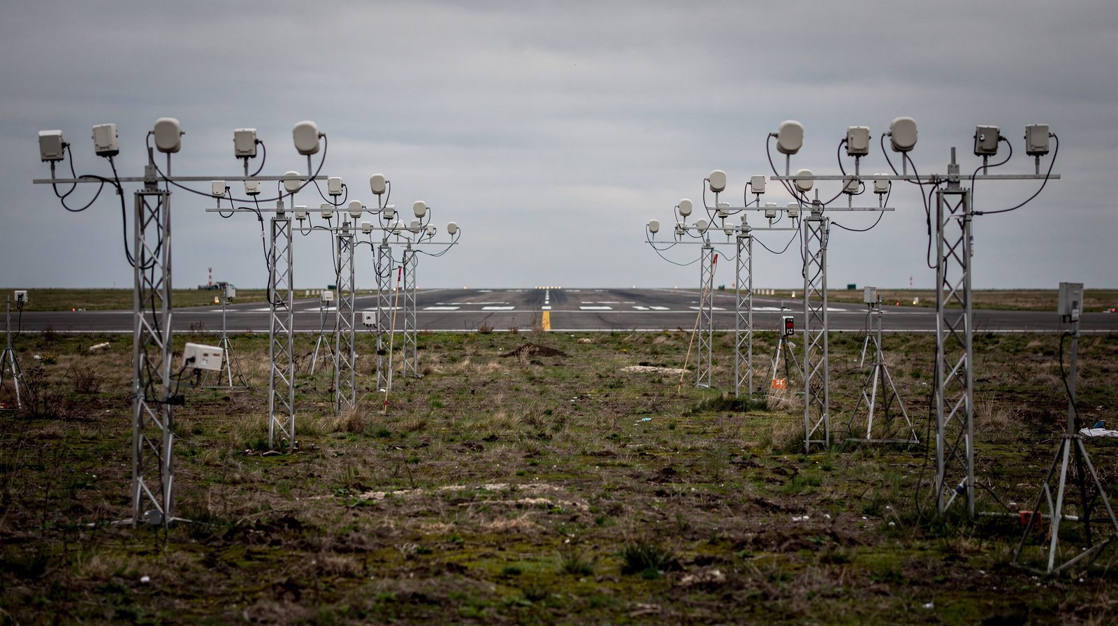
An approach lighting system is judged from the air, on the centre line, descending. So that is where we measure it. One descent flies the length of the array on the nominal glide path and returns pattern, colour, intensity build-up, coverage, dimming and the flashing row, unit by unit.
This service is bought by the person who has to sign the approach lighting rows of the visual aids protocol and knows that the array has never been looked at from where it matters. It fits the electrical manager with a periodic protocol due, the operator who just extended or converted the system and needs the pattern proven from the air, and the aerodrome answering a crew that said the approach looked incomplete.
Three outcomes are what the service is judged on, and each has a state you can check on delivery rather than a promise you have to trust.
The array as a whole is judged from the descent: the right shape for the system installed, every crossbar and side row where it belongs, the colour build-up correct, and the threshold bar reading brighter than the units ahead of it.
Each unit comes back with its colour, its intensity relative to its section, its coverage and its position, scored against the standard and against the units around it, so the fixtures to attend to are listed in the order the work should be done.
The approach lighting rows of the visual aids protocol in ICAO, EASA or FAA wording, with the flight record and the source frames attached to every finding, including the count behind the flashing rate.
An approach lighting system is not a line of identical lamps. The inspection is modelled on the real thing.
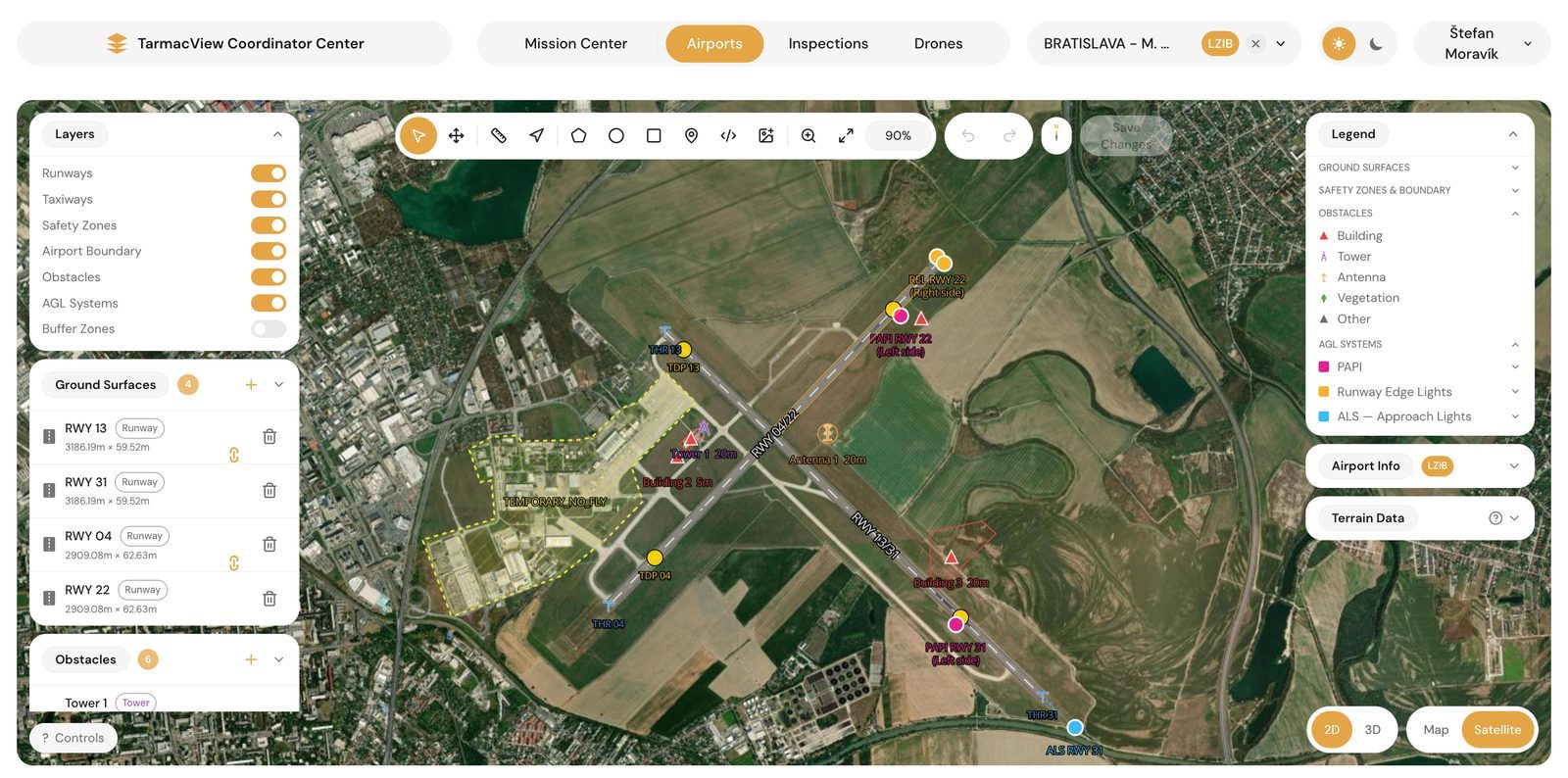
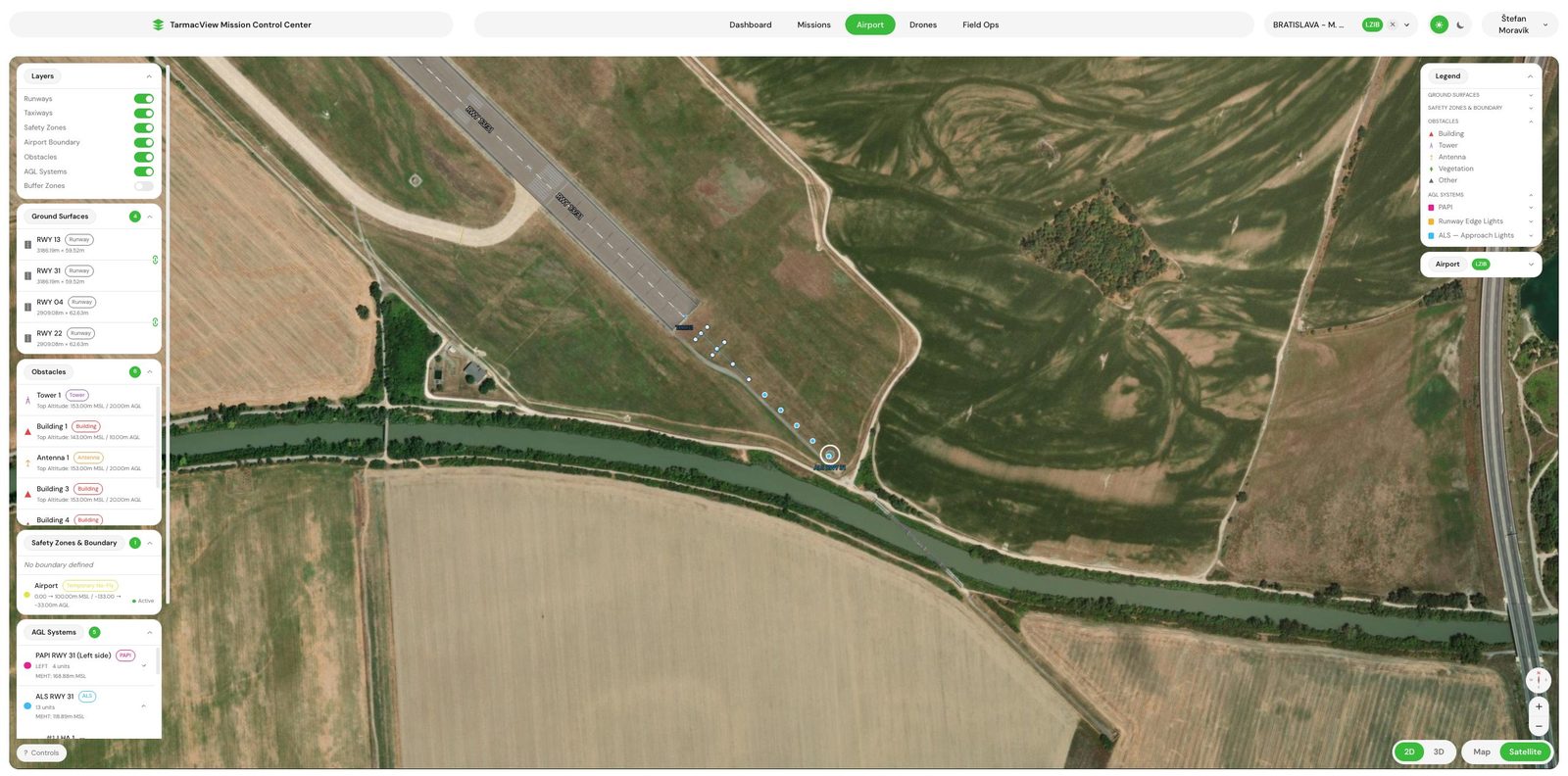
Your array is held as individual units on the extended centre line, each one carrying its ICAO Annex 14 system type, where it sits in the row, and the colour it is meant to show. Annex 14 gives an approach system two steady colours: variable white down the centre line and through the crossbars, red on the CAT II/III side row barrettes. A unit deliberately out of service is marked as such, so it is skipped rather than scored as a fault. All three Annex 14 systems are supported, simple, CAT I, and the shared CAT II/III layout.
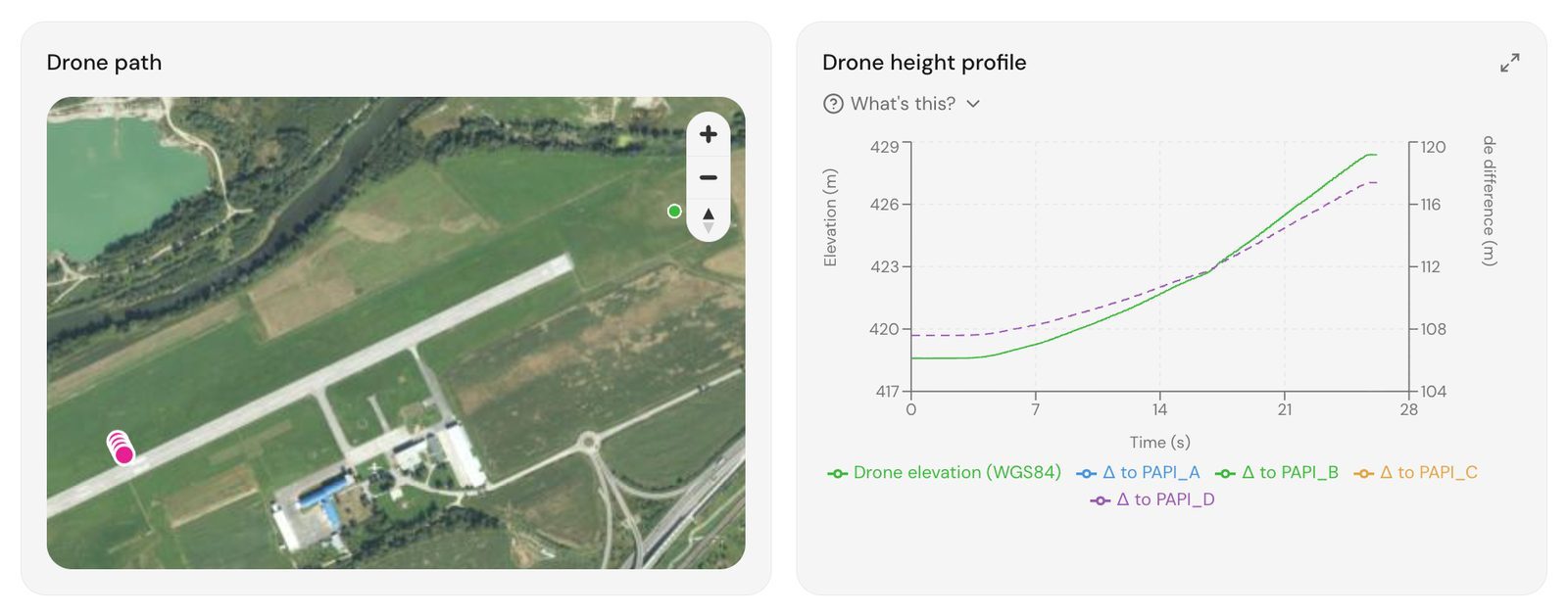
The descent starts a kilometre back of the threshold, pushed further out when it needs to be so the pass clears the outermost unit of your array by a margin, then flies down the published glide path and finishes in a hover at the minimum eye height over the threshold. It opens with a standing observation off the end of the array, which is where the attenuation and dimming steps are stepped through and where the sequenced flashing row is timed. Because the drone can hold a fixed point, a flashing row can be counted and a dimming step can be watched settle, neither of which a moving aircraft can do.
The approach lighting rows of the visual aids protocol, each with the tolerance it is judged against.
The approach pattern is the correct shape for the system installed, with every crossbar and side row where it belongs.
Each unit shows the colour its position calls for, variable white on the centre line and crossbars, red on the CAT II/III side rows.
Intensity rises through the approach to the point where the threshold bar reads brighter than the approach units ahead of it, with all units set symmetrically.
The pattern stays visible across the sector either side of the runway axis, measured out from the end of the array.
The pattern stays visible on the runway axis through the whole approach elevation band.
Every unit changes intensity together and by the commanded step, and the runway system stays visible alongside it rather than being washed out.
Intensity is sufficient, the units fire in the direction of flight toward the threshold, and the rate is correct.
The visual guidance seen over the threshold matches the published minimum eye height.
No light on the approach can be mistaken for part of the system, and none dazzles the crew.
You name the runway ends, the system type on each, the published glide path and minimum eye height, and any units out of service. We agree the intensity steps to be checked and the protocol template your authority wants. Output is a scope note. If the array's layout is not documented, the first visit records it.
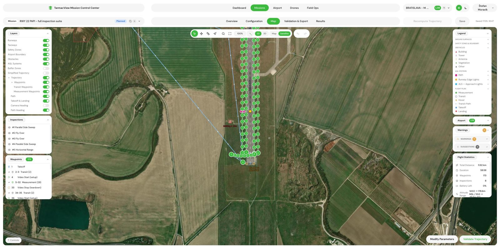
The array is modelled unit by unit from the layout and the system type, and the descent, the hover point off the end of the array and the coverage sweep are generated from it, so the outermost unit is cleared by a margin and every unit is framed. Output is a validated mission, a capture window request to your tower and a request to your lighting control room for the steps.
Flown between aircraft movements, about an hour on site per system. The hover off the end of the array comes first, for the dimming steps and the flashing row, then the descent down the published glide path to the hover over the threshold. If a movement interrupts a pass, the pass is reflown unchanged.
Each unit is tracked through the descent and its colour, relative intensity, coverage and position are extracted. The flashing row is counted over many cycles from the hover footage. Every figure is set against the array, so a unit is scored both against the standard and against its section. Uncertain frames are held for review rather than dropped.
The approach lighting rows of the visual aids protocol are filled in your authority's wording, with a figure and a verdict per unit, the pattern verdict from the descent and the flashing count. Delivered the same day, with the flight record and the source frames attached.
We walk your electrical manager through the units that sit furthest from their section and anything the descent showed as a gap. Anything disputed is re-examined against the retained footage rather than re-flown.
An approach lighting system is specified as a pattern seen from a moving point, and a pattern can be wrong in ways no fixture reveals. Every crossbar can be lit and the array still reads as a gap if one barrette is aimed low, or as two systems if the light intensity does not build toward the threshold. The inspection therefore flies the pattern as the crew flies it, on the extended centreline at the nominal glide path , and the pattern verdict is what the descent shows. The per-unit figures come from the same footage, with each unit tracked through the descent and scored against its own section of the array.
The static checks are done from a hover, and that is where a drone earns its place. The sequenced flashing lights are counted over many cycles from a fixed point off the end of the array, and their direction is read from the sequence itself. A dimming step is commanded and watched settle, with the runway lights in the same frame, so the row of the protocol that asks whether the runway system stays visible beside the approach system is answered by looking rather than by assumption.
The intensity figures are given both ways, in candela per unit and as a ratio of unit to its section and section to section, which is what the build-up and symmetry rows ask for. The camera is characterised against a calibrated source in the laboratory before it flies, and each candela value is corrected for the measured range to the unit and for the atmospheric transmission on the day, with the correction printed beside it. That is a measurement in absolute units, not a certificate. Certified photometry of an individual fixture still needs a calibrated instrument at the unit, and it stays outside this service. The chromaticity of each unit is read from the same footage, which is how a red side row barrette that has drifted toward orange is caught, and each unit’s position comes from RTK positioning , so a unit that has been moved or reinstalled off the line is named.
Retained footage is what makes a disputed finding checkable. If your inspector questions the flashing count or a unit’s figure, the frames are still there, and the count or the figure can be redone in front of them. That is also what lets the next visit report change, unit by unit, rather than a fresh opinion of the array.
There is no published rate for this service, because a simple approach system with a handful of units and a CAT II/III array of several hundred are different days of work off the same method. The quote gives your figure, and the pricing page describes the combined visit.
Three things can stop or degrade an inspection, and each has an owner.
The colour and intensity of a unit have to be read cleanly along a kilometre of approach, so fog, precipitation and low sun on the axis stop the capture. Wind above the drone's limit stops it too. The mission is flown when the window opens rather than measured through the weather.
The capture needs tower coordination, an escort at most aerodromes, and a control room that can command the intensity steps and the flashing system while the drone holds off the end of the array. The approach may also cross land outside the aerodrome boundary, which is a permission the operator is best placed to arrange.
A unit is scored against the system type, its row and its expected colour. If units were added, removed or reconfigured since the layout was documented, the scoring is against the wrong array. We agree at scoping whose layout is used, and a first visit without one records it.
Drone inspection of runway edge lights. Intensity, colour, beam shape and position measured for every unit, with a same-day protocol to ICAO, EASA or…
What an approach lighting system does for the crew, what Annex 14 asks of it in service, and why 900 metres of array off the airport is hard to…
Drone PAPI inspection. Each unit's transition angle, colour, intensity balance and surveyed position measured, with a same-day protocol to ICAO, EASA…
Send the aerodrome, the runway ends with an approach lighting system and which system each one is. That is enough to scope. You get a written scope note and a price back within two working days, and the scope note is not binding until you accept it.
Cookie Consent
We use cookies to enhance your browsing experience and analyze our traffic. See our privacy policy.