Runway Edge Light Inspection: What ICAO Requires and How It Is Measured
What ICAO Annex 14 requires of runway edge lights, what it leaves open, and how intensity, colour and coverage are actually measured in the field.
 EDGE LIGHT · DUSK
What the standard is actually specifying
From a vehicle at 30 km/h, a row of runway edge lights reads as binary. Lit or dark. That is not what the standard specifies, and it is not what an inspection has to answer.
Annex 14 Volume I sets the geometry and the colour of the row precisely, sets the intensity distribution each fixture has to produce, and then says almost nothing about how any of it gets verified once the fixture is bolted down. Verification is left to the state and the operator. That gap is where most edge light findings live, because a row can sit inside every geometric requirement in the standard and still be well outside the photometric one.
Spacing and geometry
Edge lights run in two parallel rows along the full length of the runway, at uniform intervals. For an instrument runway the interval is not more than 60 m. For a non-instrument runway it is not more than 100 m. The rows sit close to the pavement edge, typically 0.6–3 m outboard of it, and elevated fixtures are kept low, no more than about 66 cm above ground, so that a wing or a nose gear passing outside the edge does not strike one. Every elevated unit is frangible.
Geometry is the part an inspection can settle without photometry. A surveyed position for each unit gives spacing, alignment against the runway axis, and the gaps left by units that were removed and never reinstalled. It is also the part that drifts quietly, because rows get relaid in sections after resurfacing, and the section joins are where the interval slips.
Colour
Colour is prescriptive, and it is where two rule sets diverge, which matters if your airport reports to more than one authority.
| Zone | ICAO Annex 14 | FAA practice |
|---|---|---|
| Main length | Variable white | Variable white |
| Caution zone | Yellow over the last 600 m or one third of the runway length, whichever is less | Yellow over the last 2,000 ft or half the runway length, whichever is less |
| End of usable surface | Red, carried by the runway end lights | Red, carried by the runway end lights |
Both caution zone rules are conditioned on runway type and length, so read your own authority’s clause rather than the shorthand. The point of the zone is not brightness, it is the only cue the row gives about runway remaining, and a filter that has bleached toward white removes that cue while the fixture is still at full output. Chromaticity is measurable, which means it can be reported as CIE x,y coordinates instead of as an opinion about the shade.
Intensity and coverage
This is the part that cannot be judged by eye at all.
What the standard fixes is not a lamp wattage. It is a distribution: a required luminous intensity in candela, held across a defined horizontal and vertical sector around the beam axis. A fixture is compliant when it puts enough light into the volume of space a crew’s eyes will occupy, not when the lamp is on.
Those sectors are narrow. An edge light beam is elongated along the runway and thin in elevation, because that is where the eyes are. Our own protocol judges horizontal coverage against a minimum of ±15° either side of the axis and vertical coverage from 0° to 15°, with intensity at 85 per cent or better of nominal and all three commanded dimming steps reproduced. A fixture knocked a few degrees out of true by a snow plough still lights the pavement beside it and still fails the sector.
The standard also assumes the row is dimmable. Intensity control through constant current regulators is what makes one row usable in fog and on a clear night, and the commanded steps are part of what has to be verified. A row that reaches full output but flattens between steps is a finding, because the relative brightness against the approach lighting is exactly what the steps exist to preserve.
Serviceability is not performance
Annex 14 draws a line here worth quoting, because most airfield practice sits on the wrong side of it.
A light is deemed unserviceable when the mean intensity of its main beam falls below 50 per cent of the value the standard specifies. Not when it goes dark. A fixture at 55 per cent output is serviceable by that definition, is indistinguishable from its neighbours to a driver, and is the fixture that will be unserviceable next quarter. The standard also refuses to permit two unserviceable lights adjacent to one another, which is a statement about the pattern rather than about any single unit.
That definition is only usable if somebody measures. It is the reason a walk-down and a photometric measurement are not the same activity, and why the first cannot stand in for the second.
| Serviceability check | Photometric measurement | |
|---|---|---|
| Question answered | Is the unit lit | How much light, and where |
| Instrument | Eye, sometimes a circuit monitor | Calibrated photometer or imaging photometry |
| Finds a dark unit | ✓ | ✓ |
| Finds a unit at 55 per cent | ✗ | ✓ |
| Finds beam tilt or rotation | Rarely | ✓ |
| Finds a faded colour filter | Sometimes | ✓, as CIE x,y |
| Output | Pass or fail per unit | A value per unit, comparable over time |
| Typical interval | Daily to weekly | Annual to semi-annual |
Circuit monitoring narrows that gap without closing it. An airfield lighting control and monitoring system reports lamp current and open circuits, so it finds a failed unit within minutes and finds nothing at all about a dirty lens, a rotated fixture, or a filter that has bleached.
How the measurement is actually made
Photometric testing of an installed fixture is a directional measurement, and that is the whole difficulty. Laboratory practice puts the fixture on a goniophotometer and maps intensity across angles. In the field the fixture cannot be moved, so the instrument moves instead, and the geometry has to be known well enough that a reading can be attributed to an angle.
Three approaches are in service.
Fixed-point photometry. A calibrated photometer at a surveyed standoff, reading illuminance at a known distance and converting to intensity. Accurate per unit, slow per row, and it usually means closing the runway.
Mobile photometry. Sensors on a vehicle driven at a fixed offset from the row. It covers a row quickly, and it reduces the beam to whatever the vehicle’s fixed height and lateral offset happen to sample, which is one slice through a three-dimensional distribution.
Airborne imaging photometry. The row is flown and intensity recovered from calibrated imagery, with the drone’s position fixed by RTK to roughly a centimetre. Because the aircraft can be put where the pilot’s eyes will be, it samples the sector rather than one slice of it, and the approach arc can be flown at glide path height looking back down the runway. That is how we inspect an edge light row , and the reason is coverage rather than speed, though it is also faster.
All three are only as good as the calibration chain behind them and the geometry in front of them. A reading without a surveyed position is a brightness impression with a decimal point attached.
What degrades, and how it presents
Edge light degradation is rarely dramatic. Ranked by how often it turns up and how badly a visual check handles it:
| Failure mode | How it presents | Caught on a walk-down |
|---|---|---|
| Lens soiling, rubber and de-icer film | Gradual loss across a run of fixtures | ✗ |
| Optic and filter ageing | Output down, colour drifting | ✗ |
| Mechanical misalignment | Full output, wrong sector | Rarely |
| Water ingress, seal failure | Intermittent, corrodes the optic | Sometimes |
| Lamp or driver end of life | Output falls, then dark | Only at the end |
| Circuit fault | Whole section dark | ✓ |
The first two are the common case, and neither announces itself. Soiling is regional along the row, so it takes down a run of consecutive fixtures together, which is precisely the pattern the adjacent-lights rule exists to prevent.
LED fixtures changed the shape of this problem. Rated life runs from 25,000 to well over 100,000 hours against 1,000 to 2,000 hours for the incandescent lamps they replaced, so the scheduled group relamping that used to reset a row’s photometric baseline every year or two mostly stopped happening. LEDs do not conveniently fail to dark. They dim slowly, and a row that never gets relamped never gets measured either, which is how a whole row drifts down together and still looks healthy, because nothing in it is worse than anything else.
In-pavement lights sit at the extreme of that. Flush fixtures take direct wheel loading, standing water and every plough blade on the field, and guidance material puts them on a tighter measurement interval than elevated units for exactly that reason. An elevated edge light has an easier life and a longer defensible interval, but an interval only means something if a measurement happens at the end of it.
Guidance also offers a working threshold below the compliance one. A light is unserviceable below 50 per cent, and it is worth replacing once output has fallen to around 70 per cent. The distance between those two numbers is your planning window.
What the inspection has to leave behind
A report that says the row passed is not evidence. What an authority can act on, and what a maintenance team can work from, is per-unit and comparable.
For each fixture, at minimum: a surveyed position, a measured intensity with the distance and angle it was taken at, the beam’s horizontal and vertical extent against the required sector, CIE chromaticity, the dimming step it was measured on, and a timestamp. Then the row-level results that no single unit carries: spacing against the surveyed design, any adjacent low or dark units, and each unit scored against its neighbours, which is what surfaces the fixture running well under a row that is otherwise fine.
And the previous inspection. One measurement tells you whether a unit complies today. Two tell you the slope, which is what turns a compliance record into a maintenance plan. The same argument applies to the approach path indicators, and we have written separately about what Annex 14 asks of a PAPI .
Where this leaves an operator
Annex 14 gives you an unambiguous definition of failure and no method for detecting it. Nothing in the standard fixes a schedule on which the intensity of an installed edge light must be measured, and in practice a great many rows are inspected only by eye, by someone driving past them.
The honest position is that a lit row proves very little. A measured row, unit by unit, with a number against each fixture and a previous number to compare it to, is the only version of this that survives an audit or predicts a failure. Obtaining that measurement is no longer difficult. It is mostly still not being obtained.
Founded by flight-inspection veterans who spent decades measuring PAPI lights for aviation authorities across Europe.
Learn more
Related terms
03 TERMSRunway Edge Light: HIRL, MIRL and LIRL Explained
Runway edge lights mark a runway's edges in white, yellow and red. Spacing, colour and intensity per CS-ADR-DSN, Annex 14 and FAA, and HIRL, MIRL and LIRL.
Side Light (Edge Light)
A side light, also called an edge light, is a fixed aeronautical ground light installed along the edges of runways, taxiways, aprons, helipads, or safety areas to define operational boundaries. These are essential for safe aircraft movements at night or in low-visibility conditions, and follow strict ICAO and FAA standards regarding color, intensity, and placement.
Edge Light
Edge lights are airport lighting fixtures marking the boundaries of runways, taxiways, and aprons, as regulated by ICAO Annex 14 and FAA standards. They provide critical visual guidance for pilots and ground vehicles, ensuring safety and operational clarity in darkness or low visibility.
Further reading
03 ARTICLES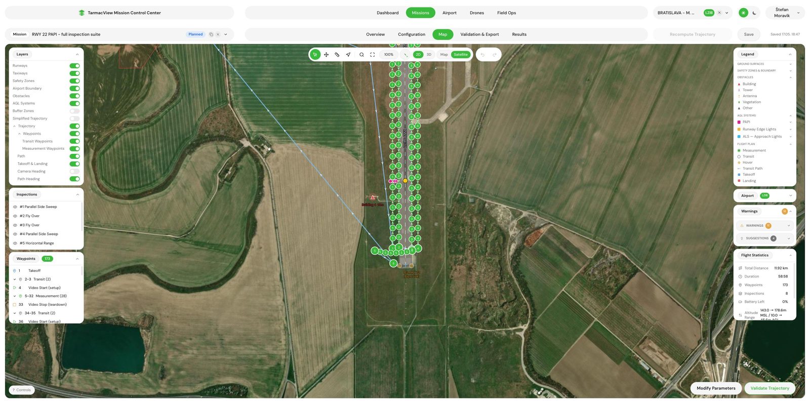
Runway Edge Lights Inspection by Drone, Unit by Unit
Drone inspection of runway edge lights. Intensity, colour, beam shape and position measured for every unit, with a same-day protocol to ICAO, EASA or…
Airfield Marking Inspection: What a Drone Survey Actually Measures
Presence, geometry and conspicuity fail separately. What a nadir drone survey measures on airfield markings, and what needs a ground instrument.
Approach Lighting System Inspection
What an approach lighting system does for the crew, what Annex 14 asks of it in service, and why 900 metres of array off the airport is hard to…