What is an Aiming Angle?
An aiming angle is the angle at which a light fixture points its beam axis, set from a reference line or plane.
An airfield light sends most of its light in one direction. The aiming angle sets that direction. Two numbers define it, one in the horizontal plane and one in the vertical plane.
Horizontal and vertical aiming
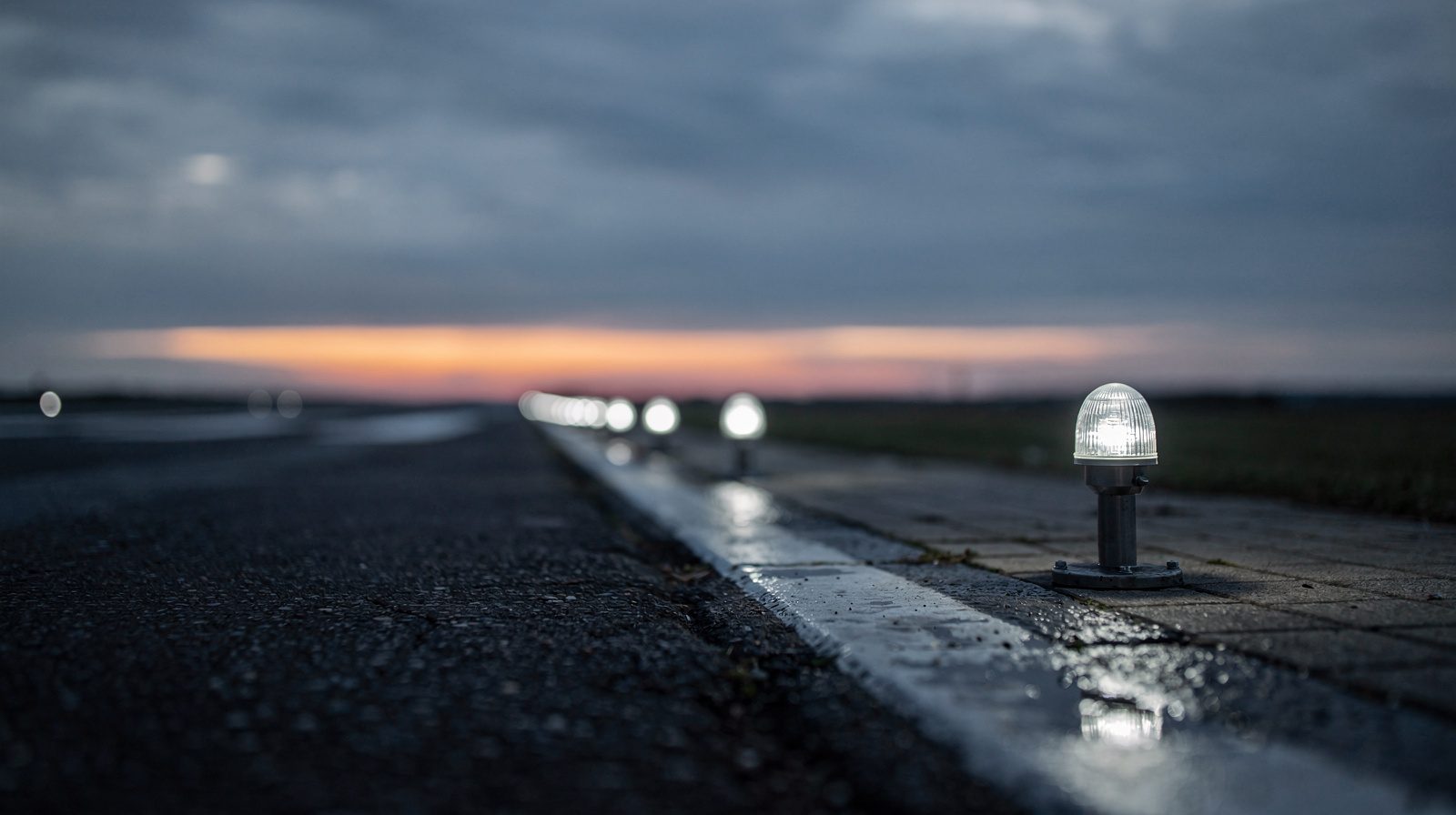
- Horizontal aiming. The standards call a horizontal angle toward a line a toe-in. A runway edge light is toed in toward the runway centreline. A light on a taxiway curve is toed in with respect to the tangent of the curve (CS ADR-DSN Figures U-18 and U-20).
- Vertical aiming. The vertical angle is measured up from the horizontal, or from the slope of the surface. For taxiway lights, CS ADR-DSN measures vertical angles from the longitudinal slope of the taxiway surface. It measures horizontal angles from the vertical plane through the taxiway centre line, or from the tangent on a curve.
- Reference. The reference differs by light type. For a PAPI the vertical reference is the glide path. For a runway edge light the horizontal reference is the runway centreline.
Aiming angles by light type
The values below are the ones that the sources state. Many lights have more detail in the manufacturer’s instructions. The FAA tells the installer to follow those instructions for the toe-in of runway edge lights (AC 150/5340-30J, 2.3.1.2.1).
| Light | Horizontal aim | Vertical aim | Source |
|---|---|---|---|
| Runway edge light, runway 45 m wide | Toe-in 3.5 degrees | Not stated in the figure | Annex 14 Figure A2-9, CS ADR-DSN Figure U-13 |
| Runway edge light, runway 60 m wide | Toe-in 4.5 degrees | Not stated in the figure | Annex 14 Figure A2-10, CS ADR-DSN Figure U-14 |
| Runway edge light (FAA) | 3.5 degrees toward the centerline | 4 degrees up from horizontal | AC 150/5340-26C, 5.3.2 item i |
| Touchdown zone light | Toed 4 degrees toward the centerline | Not stated | CS ADR-DSN Figure U-9, AC 150/5340-30J 3.3.2.3 |
| Approach side row and threshold wing bar | Toe-in 2 degrees | Not stated | CS ADR-DSN Figures U-6 and U-8 |
| Approach crossbar lights beyond 22.5 m from the centre line | Toe-in 2 degrees. All other approach lights parallel to the runway centre line | Set so that the main beam covers a stated vertical range for each distance from the threshold | CS ADR-DSN Figure U-5 notes |
| Taxiway centre line light on a curve | Toed in 15.75 degrees with respect to the tangent (17 degrees for the high intensity light in Figure U-23) | Not stated | CS ADR-DSN Figures U-18, U-20 and U-23 |
| Elevated runway guard light | Toward the cockpit of an aircraft 45 to 60 m (150 to 200 ft) from the holding position | 5 to 10 degrees above the horizontal | AC 150/5340-30J, 4.4.6 |
| Elevated stop bar light | Axis crosses the taxiway centerline 37 to 52 m (120 to 170 ft) from the holding position | 5 to 10 degrees above the horizontal | AC 150/5340-30J, 4.5.5 |
| Runway end identifier light | 15 degrees outward from a line parallel to the runway centerline | 10 degrees above the horizontal | AC 150/5340-30J, Figure A-79 note 4 |
| MALSF approach light | Beam axis parallel to the runway centerline | Intercepts an assumed 3 degree glide slope 487.6 m (1,600 ft) in advance of the light | AC 150/5340-30J, Figure A-78 note 4 |
The runway edge light page covers the system. The directional light page covers lights that send their output in one direction.
PAPI aiming
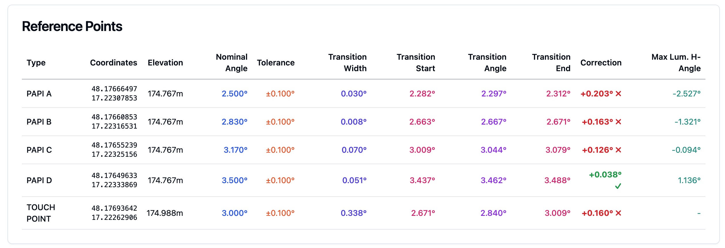
A PAPI differs from the lights above because its vertical aiming angle sets the approach slope that the pilot sees. The FAA gives the aiming angle of each unit in minutes of arc relative to the pre-selected glide path.
| Unit | Four-box L-880, standard installation | Two-box L-881 |
|---|---|---|
| Nearest the runway | 30’ above the glide path | 15’ above the glide path |
| Next unit | 10’ above | No unit |
| Next unit | 10’ below | No unit |
| Farthest from the runway | 30’ below | 15’ below the glide path |
A runway with an ILS and height group 4 aircraft uses other L-880 values. They are 35’, 15’, 15’ and 35’. One minute of arc is one sixtieth of a degree. So 30’ is 0.5 degrees. The precision approach path indicator page explains the red and white signal. The PAPI approach slope and elevation setting page explains how the slope is set.
The FAA also says to aim each unit outward into the approach zone. The line is parallel to the runway centerline, within plus or minus 1/2 degree (7.5.4.7.3).
Aiming angle and photometry
Annex 14 and CS ADR-DSN publish an isocandela diagram for each light. The diagram shows the minimum intensity at each angle around the beam axis. The collective notes to the figures say that no deviation is acceptable in the main beam pattern when the lighting fixture is properly aimed.
This links the aim to the measurement. A fixture that points the wrong way puts its main beam in the wrong place. A measurement at one point then shows a different intensity, though the light source is the same.
- The FAA says a misaligned unit looks dimmer or brighter than the units next to it (AC 150/5340-26C, 5.3.2.1.2).
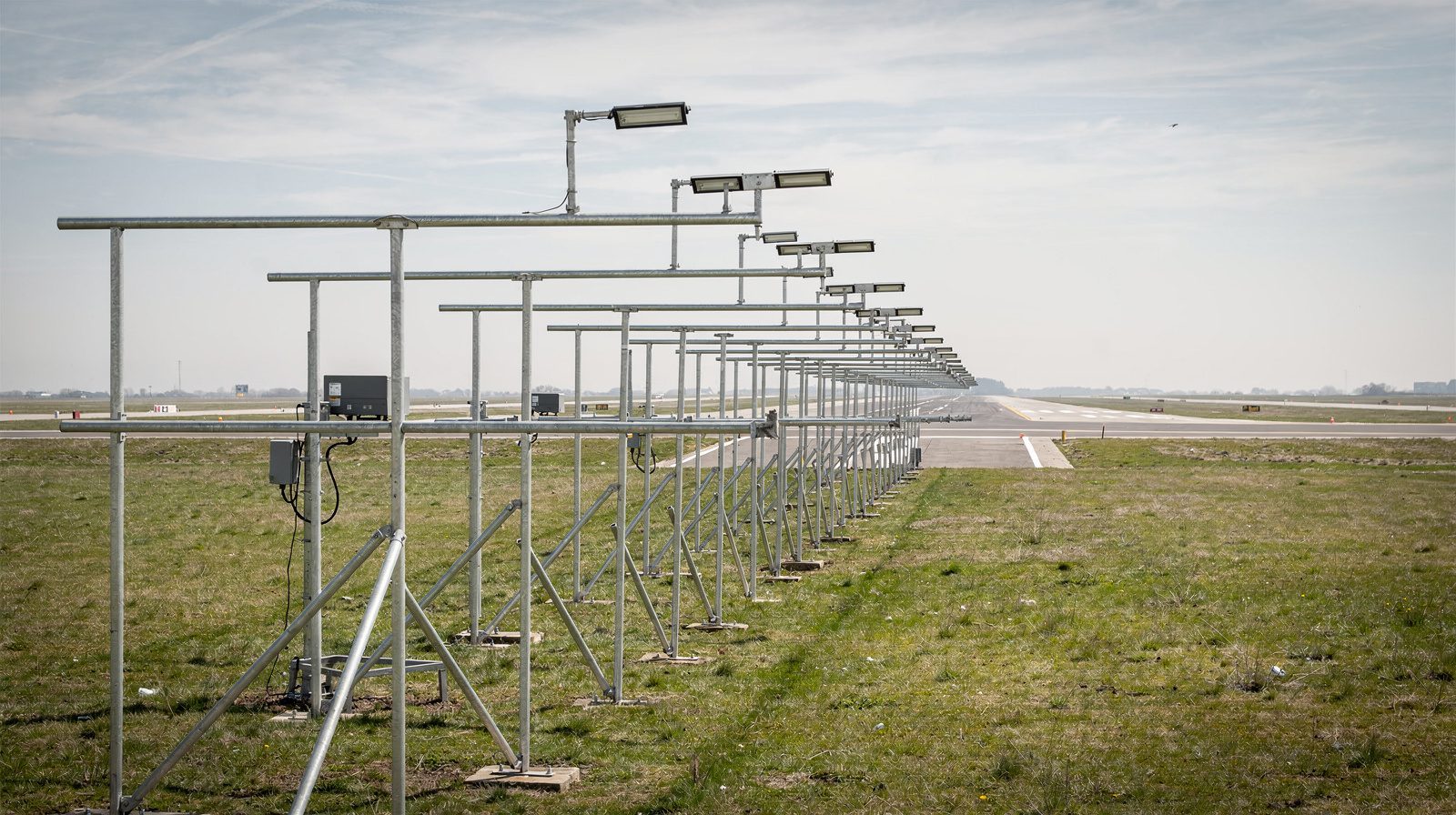
- The FAA says regular photometric measurements are the only practical way to find the misalignment errors of high intensity elevated edge lights.
- EASA asks for in-field measurement of intensity, beam spread and orientation of approach and runway lights. It says to measure all lights as far as practicable.
The photometric testing page covers the instruments and the test rates. The intensity distribution page covers the shape of the diagram.
Tolerances
- Taxiway lights. CS ADR-DSN says to install the light unit with its main beam within one-half degree of the specified requirement. The source is note g of the collective notes to Figures U-16 to U-25.
- PAPI units. The FAA gives plus or minus 1/2 degree in azimuth. EASA says to check the alignment of a visual approach slope indicator system (VASIS) at defined intervals. It says to correct errors above one minute of arc. The same paragraph covers the PAPI and the APAPI (AMC1 ADR.OPS.C.015(a) and (f)).
- Runway centerline lights. The FAA says to align them within 2 degrees of a line parallel to the runway centerline.
Aiming angle, beam angle and aiming point
Three terms use the word angle or aim, and they describe different things.
- Aiming angle gives the direction of the beam axis.
- Beam angle gives the width of the beam. The beam angle page covers it.
- Aiming point marking is a marking on a runway, which has two conspicuous stripes (CS ADR-DSN.L.540). It is not a light setting.
The glide path angle is a fourth term. It is the slope of the approach path. A PAPI aiming angle is set relative to it, but the two are not the same value.
What moves the aim
- Impact. The FAA says mowers and other vehicles can knock elevated lights out of adjustment, and that lenses can move when staff replace lamps.
- Base movement. The aim of an in-pavement light on a shallow base can come out of alignment when the base moves. A light on top of a transformer housing has a non-adjustable aim.
- Soil. The FAA says to check the aim of a PAPI often when the soil freezes or thaws or its moisture changes. Clay soils are the example it gives.
The light fixture page covers the base and the fixture types.
Checking and correcting the aim
If a light looks dimmer or brighter than its neighbours, check its aim. The FAA gives these methods:
- Look at the lights at night, or measure them with mobile photometric equipment.
- For in-pavement lights without mobile equipment, turn the lights on in fog. The fog shows the beam, and a mis-aimed light is easy to see.
- For touchdown zone lights, stand on the centreline and look at the bars on both sides. A light that looks dimmer or brighter than the next one may be mis-aimed.
- For a PAPI, use the aiming instrument that the maker supplies. Record the angle and the date in a maintenance log.
- Do photometric testing before and after realignment, to see if the work was needed and if it worked.
EASA also recommends special flight checks after major maintenance of, or changes to, the lighting systems.
TarmacView inspects PAPI and other airfield lights with a drone and reports each light relative to its neighbours. It does not measure intensity in candela. A drone inspection does not replace the photometric test or the aiming instrument. See the drone airport inspection solution.
Frequently Asked Questions
- What is an aiming angle?
- An aiming angle is the angle at which a light fixture points its beam axis, set from a reference line or plane. It has a horizontal part and a vertical part. The FAA calls the beam centerline of a runway end identifier light its aiming angle. The standards for other lights call the horizontal part toe-in and the vertical part a vertical setting angle.
- What aiming angle do runway edge lights use?
- A runway edge light is toed in toward the runway centreline. The toe-in is 3.5 degrees on a runway 45 m wide. It is 4.5 degrees on a runway 60 m wide (Annex 14 Figures A2-9 and A2-10, CS ADR-DSN Figures U-13 and U-14). The FAA says the beam of a runway edge light is aimed 3.5 degrees toward the centerline and 4 degrees up from the horizontal.
- How does the aiming angle affect a photometric measurement?
- The isocandela diagrams in Annex 14 and CS ADR-DSN apply to a fixture that is properly aimed. A fixture that points the wrong way has its main beam in the wrong place, so a measurement shows a lower or higher intensity. The FAA says regular photometric measurements are the only practical way to find misalignment errors in high intensity edge lights.
- What is the aiming angle of a PAPI?
- The FAA gives the vertical aiming angle of each PAPI unit in minutes of arc relative to the glide path. A four-box L-880 system has units at 30' above, 10' above, 10' below and 30' below the glide path in the standard installation. A two-box L-881 system has units at 15' above and 15' below. Each unit also points outward on a line parallel to the runway centerline, within plus or minus 1/2 degree.
- What tolerance applies to an aiming angle?
- The tolerance depends on the light. CS ADR-DSN says a taxiway light unit should be installed so that its main beam is within one-half degree of the specified requirement. The FAA gives plus or minus 1/2 degree in azimuth for PAPI units. For runway centerline lights it gives 2 degrees from a line parallel to the runway centerline. EASA says to correct alignment errors above one minute of arc in a visual approach slope indicator system, which includes the PAPI.
- What is the difference between an aiming angle and a beam angle?
- The aiming angle gives the direction of the beam axis. The beam angle gives how wide the beam is. A light can have the right beam angle and the wrong aiming angle. An aiming angle is also not an aiming point marking, which is a pair of stripes painted on a runway.
- What moves the aiming angle of an airfield light?
- Impacts and movement of the base move it. The FAA says mowers and other vehicles can knock elevated lights out of adjustment. It says the aim of in-pavement lights on shallow bases can shift when the bases move. It also says to check PAPI aiming often when the soil freezes or thaws or its moisture changes, especially clay soils.
- How do you check the aiming angle of a light?
- The method depends on the light. For a PAPI, staff use the aiming instrument that the maker supplies and record the angle and the date. For runway lights, staff look at the lights at night for a unit that is dimmer or brighter than its neighbours. They may also use mobile photometric equipment. EASA asks for in-field measurement of intensity, beam spread and orientation.
References
- icao-annex-14-vol1
- Annex 14 to the Convention on International Civil Aviation, Aerodromes, Volume I, Aerodrome Design and Operations, Ninth Edition (July 2022, consolidated with later amendments) ICAO
- easa-ear-aerodromes
- Easy Access Rules for Aerodromes (Regulation (EU) No 139/2014), including CS-ADR-DSN Issue 7 EASA
- faa-ac-150-5340-30j
- AC 150/5340-30J, Design and Installation Details for Airport Visual Aids FAA
- faa-ac-150-5340-26c
- AC 150/5340-26C, Maintenance of Airport Visual Aid Facilities FAA
This is a reference entry. TarmacView provides drone inspection services and doesn't sell the equipment or materials described in this glossary.