FAA AC 150/5340-30: Design and Installation of Airport Visual Aids
What FAA AC 150/5340-30J sets for airport lighting installation: edge, centreline, taxiway and PAPI tolerances, AIP and PFC status, and what to check on site.
- 01 The Application paragraph makes the circular mandatory for projects funded through the Airport Improvement Program or Passenger Facility Charges. In general it is otherwise recommended guidance, and the FAA calls its configurations an acceptable means of meeting 14 CFR 139.311.
- 02 It is an installation document. Maintenance goes to AC 150/5340-26 (paragraphs 6.4 and 12.14) and fixture performance to the referenced 150/5345 specifications.
- 03 Paragraph 7.5.4.7 sets the PAPI installation tolerances: inboard unit 50 ft from the runway edge, units 20 to 30 ft apart, azimuth within half a degree and beam centres within 1 inch of a horizontal plane.
- 04 Paragraph 1.4 bars mixing LED and incandescent fixtures of the same type, PAPI and runway edge lights included, because colour and brightness can differ.
- 05 The circular never mentions drones. Insulation, grounding and base work are electrical or civil checks that stay on the ground.
On this page · 10 sections
The FAA keeps its installation details for airport visual aids in one advisory circular. AC 150/5340-30J is dated 12 February 2018, was initiated by AAS-100 and cancels the July 2014 edition, 30H. Its thirteen chapters open with an introduction. Chapters 2 to 13 run from runway and taxiway edge lights to standby power, pavement types, mounting bases and power distribution, with typical installation drawings in Appendix E.
What the circular is, and who it binds
The Application paragraph, paragraph 3 of the front matter, sets the status. The FAA “recommends” the guidance and specifications in the circular. In general, use is not mandatory. It is mandatory for all projects funded with federal grant money through the Airport Improvement Program (AIP) or with revenue from the Passenger Facility Charges (PFC) Program. The link is made through Grant Assurance No. 34, Policies, Standards, and Specifications, and PFC Assurance No. 9, Standards and Specifications.
The same paragraph adds that all lighting configurations in the circular are “a means acceptable to the Administrator” to meet the lighting requirements of 14 CFR 139.311, Marking, Signs and Lighting. That is a statement about acceptable means, not a rule that every Part 139 airport must follow the circular line by line.
Paragraph 1.2 reads more firmly. It calls the contents “standards the FAA requires in all applications involving airport development of this nature” and says they “must be met where lighting systems are required for FAA-developed procedures.” The text does not say how that sentence sits beside the Application paragraph for an installation paid for without AIP or PFC money. This page does not settle it either.
Inside the text, the verbs carry the weight. “Must” and “must not” mark hard limits, such as the 200 ft maximum spacing of runway edge lights. “Should” and “we recommend” mark softer ones, such as setting edge lights 10 ft from the pavement edge on runways used by jets. Paragraph 5 adds that metric values may not be exact conversions, and that the English dimensions govern.
AC 150/5340-30J at a glance
- Issuer
- Federal Aviation Administration, initiated by AAS-100. Dated 12 February 2018, cancels 30H.
- Status
- Recommended guidance. Mandatory for AIP-funded and PFC-funded projects through Grant Assurance No. 34 and PFC Assurance No. 9 (paragraph 3).
- Scope
- Installation methods, spacing, colours, aiming and tolerances. Performance specifications sit in the referenced advisory circulars (paragraph 1.1).
- Maintenance
- Left to AC 150/5340-26 (paragraphs 6.4 and 12.14). Operational tolerances are in its Appendix A (paragraph 2.6.3.5).
- Runway edge lights
- 2 to 10 ft (0.6 to 3 m) from full-strength pavement, spacing not more than 200 ft (61 m), with a 400 ft (122 m) limit at some intersections. LIRL on visual runways, MIRL on visual or non-precision, HIRL on precision (paragraphs 2.2, 2.3.1.2.1 and 2.3.1.2.2).
- Runway centreline lights
- 50 ft (15 m) intervals with a longitudinal tolerance of 2 ft (0.6 m) (paragraph 3.3.1.1).
- Taxiway edge lights
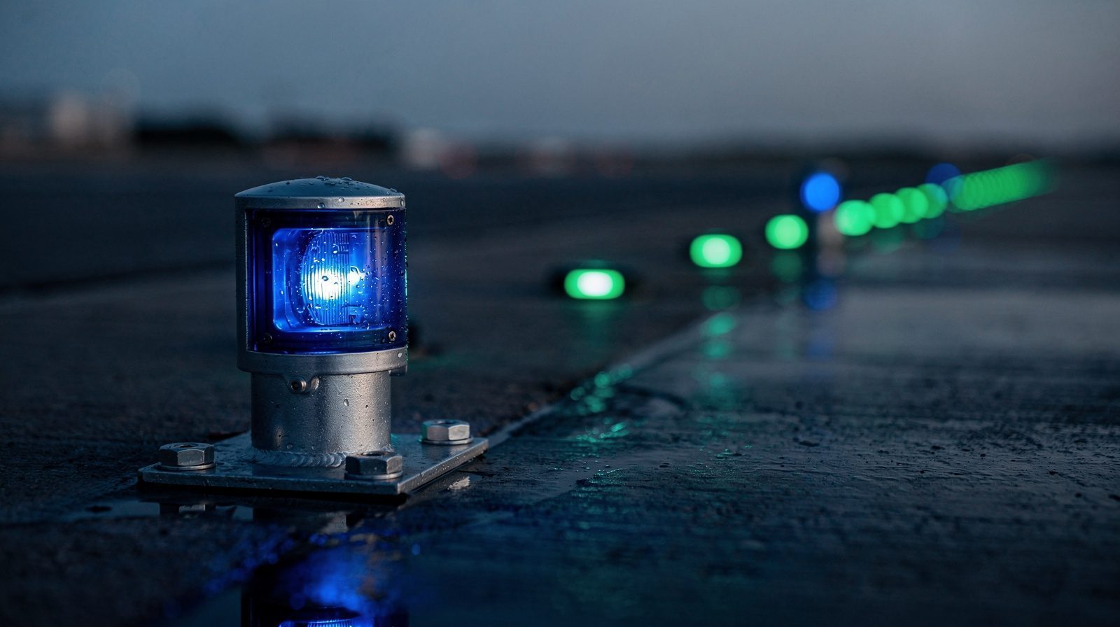
- Blue. Standard installed height of elevated fixtures not more than 14 inches (355.60 mm) (paragraphs 2.5.1 and 2.5.2).
- PAPI
- Inboard unit 50 ft (+10, -0) from the runway edge, units 20 to 30 ft apart, azimuth within half a degree (paragraph 7.5.4.7).
- LED and incandescent
- Not to be interspersed within the same type of light (paragraph 1.4).
- Cable testing at installation
- Insulation resistance to ground not less than 50 megohms (paragraph 12.11.1).
What it covers, system by system
The circular installs the visual aids. It does not repeat each aid’s performance specification. Paragraph 1.1 sends the reader to the referenced advisory circulars for those, and to Appendix E for typical installation drawings.
Runway and taxiway edge lights (chapter 2). Paragraph 2.2 picks the system by runway. Low intensity runway lights (LIRL) go on visual runways, medium intensity (MIRL) on visual or non-precision instrument runways, and high intensity (HIRL) on precision instrument runways. Medium intensity taxiway lights go on taxiways and aprons where runway lighting is installed. Runway edge lights are white. On MIRL and HIRL runways yellow replaces white in a caution zone, the last 2,000 ft (610 m) of runway or half its length, whichever is less (paragraph 2.3.1.1.2). The edge lights sit on a line parallel to the centreline, uniformly spaced and symmetrical, and a line between opposite units is perpendicular to the centreline (paragraph 2.3.1.2.1). Paragraph 2.6.4 gives five brightness steps for HIRL , three for MIRL and one for LIRL.
Threshold and runway end lights are green outward and red toward the runway. They sit 2 to 10 ft before the threshold in two groups on 10 ft centres, three lights per group on visual runways and four on instrument runways (paragraph 2.3.2.2.1). Taxiway edge lights are blue, and Table 2-1 sets their spacing by section length. Paragraph 2.5.3.2.1 requires at least three lights on any curved edge arc of more than 30 degrees.
Runway centreline and touchdown zone lights (chapter 3). Paragraph 3.2 requires them on CAT II and CAT III runways and on CAT I runways used for landing below 2,400 ft (750 m) RVR. Centreline lights sit at 50 ft (15 m) intervals with a longitudinal tolerance of 2 ft (0.6 m). They may be offset uniformly to one side by up to 2.5 ft (0.8 m), with a tolerance of 1 inch (25.4 mm). On a new runway the light base must be at least 2 ft (0.6 m) from any pavement joint. The last 3,000 ft (900 m) is colour coded, alternating red and white from 3,000 to 1,000 ft (900 to 300 m) from the end and red in the last 1,000 ft (paragraphs 3.3.1.1 and 3.3.1.2). Touchdown zone lights are two rows of bars of three unidirectional lights, the first bars 100 ft (30 m) from the threshold, each beam toed four degrees toward the centreline (paragraph 3.3.2).
Taxiway lighting (chapter 4). Taxiway centreline lights are green, and lead-on and lead-off lights alternate green and yellow. Table 4-1 sets maximum spacing by curve radius and by whether operations go below 1,200 ft (365 m) RVR. Individual fixtures may vary by 10 percent of the specified spacing, and beams on straight portions must be parallel to the centreline within 1 degree (paragraphs 4.3.3.1 and 4.3.9). A stop bar is a row of unidirectional in-pavement red lights with an elevated red light on each side of the taxiway. In-pavement stop bar lights sit 2 ft (0.6 m) from the holding position marking with a tolerance of 2 inches and are spaced 9 ft 10 inches (3 m) apart, plus or minus 2 inches (paragraphs 4.5.2.1 and 4.5.2.3.1). Paragraph 4.1.3.3 requires stop bars for operations below 600 ft (183 m) RVR on illuminated taxiways that lead to the active runway.
Land and hold short lights, beacons and wind cones (chapters 5 and 6). A land and hold short system is a row of six or seven in-pavement unidirectional pulsing white lights across the runway at the hold-short point (paragraph 5.5). Chapter 6 covers airport rotating beacons, beacon towers, wind cones and obstruction lights.
Economy approach aids (chapter 7). The medium intensity approach lighting system with or without sequenced flashers (MALSF or MALS) has seven centreline bars of five steady lights, with a flashing light at each of the three outermost bars, extending about 1,400 ft (427 m). REIL are two flashing lights near the runway end. ODALS is seven omnidirectional sequenced strobe lights. PAPI is described in its own section below. The larger approach lighting systems are not here. Paragraph 7.3.6.1.3 sends the reader to FAA Order JO 6850.2 for MALSR, and the circular does not describe ALSF-2 or SSALR at all.
Supporting chapters. Chapter 8 covers radio control equipment, chapter 9 standby power at non-FAA airports, chapter 10 pavement types, chapter 11 fixture mounting bases, chapter 12 equipment and materials and chapter 13 power distribution and control. Appendix G covers the runway status light system and Appendix H holds legacy figures.
Revision J made several changes that matter for an installation review. Paragraph 1.6 bars non-certified devices from the high voltage series circuit. Taxiway edge light spacing was reworked around new fillet geometry. Figures 2, 3, 5 to 12 and 16 to 22 moved to Appendix H as legacy figures “for reference only, and are not for use in new design.”
PAPI siting and aiming
PAPI carries a long list of installation tolerances, and most of them are in paragraph 7.5.4.7.
The light units sit on the left side of the runway where possible (paragraph 7.5.4.1.1). The inboard unit is not less than 50 ft (15 m), plus 10 ft and minus none, from the runway edge. The distance can drop to 30 ft (10 m) on small general aviation runways used by non-jet aircraft. Units are 20 to 30 ft (6 to 9 m) apart centre to centre, and the spacing may not vary by more than 1 ft. Each unit aims outward on a line parallel to the runway centreline within half a degree. The beam centres of all units lie within 1 inch (25 mm) of a horizontal plane, and that plane is within 1 ft (0.3 m) of the runway centreline elevation at the point where the visual glide path meets the runway.
Table 7-2 gives the standard aiming angles for the four-box L-880, relative to the pre-selected glide path. The unit nearest the runway aims 30 minutes of arc above the path, the next 10 minutes above, the next 10 minutes below and the farthest 30 minutes below. For a runway with an ILS used mainly by height group 4 aircraft the figures are 35, 15, 15 and 35 minutes. Table 7-3 gives 15 minutes above and below for the two-box L-881. The standard visual glide slope is 3 degrees, and on non-jet runways it may be raised to 4 degrees for obstacle clearance (paragraph 7.5.4.3.4).
The obstacle clearance surface (OCS) starts 300 ft (90 m) in front of the PAPI and rises at one degree less than the lowest on-course aiming angle. It extends 10 degrees either side of the runway centreline to 4 NM (7.4 km) from its point of origin (paragraphs 7.5.4.4.3 and 7.5.4.4.5). Revision J changed the Figure A-81 radius label from “4 Mile” to “4 NM”. Threshold crossing height depends on the height group of the aircraft that use the runway, for example 45 ft for height group 2 (Table 7-1).
Flight inspection gets a short treatment in paragraph 7.7.6.6.4. A commissioning inspection is required for all new visual glide slope indicators with an associated instrument procedure, circling approaches included. There is no periodic inspection requirement for these indicators, though confirmation of safe operation “should be accomplished in conjunction with other flight inspections involving the associated runway.” Flight check personnel evaluate obstacle clearance within the lateral limits of the visible beam, and that evaluation may go beyond the standard OCS. The regulatory acceptance guide covers how measured transition angles relate to a programme like this.
Installation tolerances that decide whether a light is right
Several limits in chapters 3, 4, 10 and 12 are the ones a reviewer can check against a finished installation.
For in-pavement fixtures in new rigid pavement, the mounting flange of the base sits at least ¾ inch (19 mm) below the finished surface, and a maximum of three spacer rings may be stacked (paragraph 10.2). Paragraph 10.2 also sets the fixture at plus 0 to minus 1/16 inch below the low side of the pavement surface. For new flexible pavement, paragraph 10.3.12 puts the top of the fixture between flush and 1/16 inch below the pavement surface, measured at the highest edge if the fixture is not level or the pavement is crowned. Bolts are tightened to the manufacturer’s recommended torque (paragraph 10.3.14). For bolt torque maintenance, paragraph 10.2 points to paragraph 5.3.4 of AC 150/5340-26.
The inspection paragraph, 12.11, lists what to confirm on each fixture. It must be installed correctly, at the proper height, in line with its neighbours, level and properly oriented. Securing bolts are tight. Lenses are clean and unscratched. Asymmetric lenses are oriented to the runway sides and threshold. Identification numbers match the plans. Paragraph 12.11.1 adds the tests. Insulation resistance to ground of non-grounded series circuits is not less than 50 megohms, the system runs for at least half an hour while the intensity is changed, and each control is operated at least 10 times. If there is a monitoring system, it is tested by removing fixtures from the circuit until it reports an error.
Mixing LED and incandescent lights
Paragraph 1.4 is the rule an inspector is most likely to meet in the field. LED fixtures are close to single-colour emitters, aviation white excepted, and may show a different perceived colour or brightness from an equivalent filtered incandescent fixture. So LED fixtures “must not be interspersed with incandescent lights of the same type.” The circular’s example is a runway extension, where new LED centreline fixtures may not be mixed with the existing incandescent ones. A defective incandescent fixture must not be replaced by an LED one. The list of systems includes runway guard lights, touchdown zone lights, runway edge, threshold, end and stopway lights, taxiway centreline and edge lights, approach lights, stop bars, runway centreline, lead-on and lead-off lights, signs per location and PAPI.
What matters when inspecting installed lights
The circular is written for the person designing and accepting an installation, and its limits fall into two groups. Some can be seen from where a pilot sees the light, such as colour, position in the row, lit or dark and PAPI aim. The rest are measured at the fixture or in the cable.
What AC 150/5340-30J fixes, and what a drone survey can supply
| Item | What the circular fixes | What a drone survey can supply | What stays a ground or electrical task |
|---|---|---|---|
| Edge light position and spacing | 2 to 10 ft from full-strength pavement, uniform spacing, not more than 200 ft, opposite units on a perpendicular line (paragraph 2.3.1.2.1) | A surveyed position for each unit, so spacing and rows can be compared with the design drawing | Setting out against the pavement edge, and levelling each fixture |
| Colour and zones | White, yellow in the caution zone, green and red at thresholds, blue on taxiways, red and white at the runway end (paragraphs 2.3.1.1, 2.3.2.1, 2.5.1 and 3.3.1.2) | Colour against position for each unit, seen from the approach or taxi side | Reading the lens and fixture type up close |
| Centreline and touchdown zone layout | 50 ft intervals with a 2 ft tolerance, offset not more than 2.5 ft, bars of three lights toed four degrees (paragraphs 3.3.1 and 3.3.2) | Lit or dark and surveyed position for each unit | Base distance to pavement joints and optical assembly toe, measured at the fixture |
| Beam orientation (plus or minus 1 degree) | Taxiway centreline, runway guard light and stop bar beams within 1 degree of the specified direction (paragraphs 4.3.9, 4.4.4 and 4.5.3) | Output of a unit that stands out from its neighbours, as a pointer for inspection | The orientation measurement itself, and any adjustment on a 12-bolt base |
| PAPI position and aim | Unit spacing, azimuth within half a degree, beam centres within 1 inch, aiming angles from Tables 7-2 and 7-3 (paragraph 7.5.4.7) | Measured transition angles of each unit as seen from the approach | Aiming with the manufacturer's device, foundation, frangible fittings and height tolerances |
| Mixed light technology | No LED among incandescent fixtures of the same type (paragraph 1.4) | A unit whose colour or relative output stands out from its row | Identifying the fixture type and the cause |
| Base height, bolts and spacer rings | Flange at least 3/4 inch below the surface, top of fixture flush to 1/16 inch below, three rings at most, bolts to manufacturer's torque (paragraphs 10.2 and 10.3) | Nothing below the lens | All of it, by hand at the fixture |
| Cables, grounding and monitoring | Insulation resistance of at least 50 megohms, continuity, grounding and monitoring tests (paragraph 12.11.1) | Nothing. These are not visible from the air | All of it, in the vault and on the cable |
TarmacView flies airfield lighting inspection for PAPI, approach lights , runway edge lights , threshold and end lights , centreline lights and taxiway lights . Each unit gets lit or dark, colour against position, output relative to its neighbours and to the commanded step, and an RTK-surveyed position. Flights run between movements in coordination with the tower, with no closure booked. Insulation resistance, grounding, base work and anything underground are not measured. Absolute output in candela needs a calibrated photometer and is not reported. The comparison with flight inspection sets out what each method covers.
Where it sits beside AC 150/5340-26
The two circulars split the work. AC 150/5340-30J says how lights are laid out, installed and accepted. AC 150/5340-26C says how often they are checked, cleaned and measured once in service, and carries the operational tolerances in its Appendix A. Paragraphs 2.6.3.5, 6.4 and 12.14 of the installation circular all point across to it. An inspector checking an installed light uses 30J for where the light should be and which way it should face, and 26C for how it should perform and how often that is checked.
How it compares with the EASA and ICAO texts
The European framework is Regulation (EU) No 139/2014 with its certification specifications, and the lighting detail is in CS-ADR-DSN Chapter M. ICAO Annex 14, Volume I, has the matching clauses. The FAA layout is similar in intent, and differs in several numbers. Read the EU text first for European work.
- Runway edge light spacing. The FAA allows lights not more than 200 ft (61 m) apart and sets them 2 to 10 ft from the pavement edge (paragraph 2.3.1.2.1). CS ADR-DSN.M.675(b) places them along the edges or not more than 3 m outside, at intervals of not more than 60 m on an instrument runway and 100 m on a non-instrument one. Annex 14 paragraphs 5.3.9.4 and 5.3.9.6 say the same with “shall”, where the CS says “should”.
- Caution zone. The FAA substitutes yellow for the last 2,000 ft (610 m) or half the runway, whichever is less, on MIRL and HIRL runways. CS ADR-DSN.M.675(c)(1)(ii) uses 600 m or one-third of the runway length, whichever is less, at the remote end. Annex 14 paragraph 5.3.9.7 says “may show yellow”.
- Runway centreline lights. Both give about 15 m (the FAA 50 ft with a 2 ft tolerance). CS ADR-DSN.M.690(c) allows about 30 m where the serviceability level can be demonstrated and RVR is 350 m or greater, and Annex 14 paragraph 5.3.12.5 says 300 m or greater. The FAA text has no 30 m option. The maximum lateral offset is 60 cm in the EU and ICAO texts and 2.5 ft (0.8 m) in the FAA circular. The red and white zones match on a long runway. The EU and ICAO texts add a short-runway rule for runways under 1,800 m, which the FAA text does not have.
- PAPI protection surface. The FAA OCS is a 10 degree sector each side to 4 NM. CS ADR-DSN.M.655 and Table M-2 give a trapezoid with 10 or 15 percent divergence each side and a total length of 7,500 m or 15,000 m by code number and runway type.
The EASA CS-ADR-DSN page and the ICAO Annex 14 page set out those frameworks in their own terms. For how many lights may be out of service in each system, see the serviceability limits guide .
Frequently Asked Questions
- Is AC 150/5340-30J mandatory?
- Only in part. The Application paragraph says use of the circular is in general not mandatory. It is mandatory for all projects funded with federal grant money through the Airport Improvement Program and with revenue from the Passenger Facility Charges Program, citing Grant Assurance No. 34 and PFC Assurance No. 9. Paragraph 1.2 separately calls its contents standards the FAA requires in all applications involving airport development of this nature, and says they must be met where lighting systems are required for FAA-developed procedures.
- What does AC 150/5340-30J cover?
- Installation details for airport visual aids. That is runway and taxiway edge lights, runway centreline and touchdown zone lights, taxiway centreline lights, runway guard lights and stop bars, land and hold short lights, beacons, wind cones and obstruction lights, MALS and MALSF, ODALS, REIL and PAPI. It also covers standby power, mounting bases, cable and control systems. ALSF-2 and SSALR are not in it.
- Does it set maintenance intervals or light output limits?
- No. Paragraph 6.4 says maintenance must be performed per AC 150/5340-26, paragraph 12.14 refers the reader to it, and paragraph 2.6.3.5 sends the reader to its Appendix A for operational tolerances. Paragraph 1.1 says performance specifications for each aid are in the referenced advisory circulars. This one gives positions, spacing, colours, aiming and installation tolerances, plus the brightness steps of edge lights in paragraph 2.6.4.
- What are the PAPI installation tolerances?
- Paragraph 7.5.4.7 sets them. The inboard light unit sits 50 ft from the runway edge, plus 10 ft and minus none. Units are 20 to 30 ft apart centre to centre and may not differ by more than 1 ft. Each unit aims within half a degree of parallel to the centreline. Beam centres lie within 1 inch of a horizontal plane. Aiming angles come from Tables 7-2 and 7-3.
- Can LED and incandescent lights be mixed?
- Not within the same type of light. Paragraph 1.4 says LED fixtures must not be interspersed with incandescent lights of the same type, and a defective incandescent fixture must not be replaced with an LED one. The list includes runway edge, threshold and end lights, centreline, touchdown zone, taxiway, stop bar, approach lights and PAPI. The stated reason is a possible difference in perceived colour or brightness.
- How does it compare with CS-ADR-DSN and ICAO Annex 14?
- The layouts are close but not identical. For runway edge lights the FAA allows 200 ft (61 m) spacing and sets lights 2 to 10 ft from the pavement edge. CS ADR-DSN.M.675 and Annex 14 paragraphs 5.3.9.4 and 5.3.9.6 allow 60 m on an instrument runway and 100 m on a non-instrument one, with lights not more than 3 m outside the edge. The caution zone is also defined differently.
- Does the circular allow drones for checking installed lights?
- It is silent on drones. It describes how lights are installed, tested by the contractor and flight-inspected where a PAPI has an instrument procedure. Whether a survey method serves an airport's acceptance or maintenance programme is for that airport and the FAA to decide, not for the circular or a survey provider.
References
- faa-ac-150-5340-30j
- AC 150/5340-30J, Design and Installation Details for Airport Visual Aids Federal Aviation Administration
- easa-ear-aerodromes
- Easy Access Rules for Aerodromes (Regulation (EU) No 139/2014) European Union Aviation Safety Agency
- icao-annex-14-vol-1
- Annex 14 to the Convention on International Civil Aviation, Volume I, Aerodrome Design and Operations International Civil Aviation Organization
- faa-ac-150-5340-26c
- AC 150/5340-26C, Maintenance of Airport Visual Aid Facilities Federal Aviation Administration