What is a Runway Edge Light?
Along a runway used at night, the two rows of white lights either side of the pavement are the runway edge lights. A crew picks them up first on an approach and holds them longest on the take-off roll, and an inspector measures them most often, because there are more of them than any other fixture on the runway.
Definition
CS-ADR-DSN and Annex 14 define runway edge lights by what they mark: the lateral limits of the usable portion of a runway. Each is a fixed light showing variable white, mounted on or just outside the runway edge, in two parallel rows the same distance from the centreline. Opposite lights sit on a line at right angles to the runway axis, so the rows read as a pair of rails rather than a scatter of points.
The colour changes only where the meaning changes. Where a threshold is displaced, the lights between the runway start and the displaced threshold show red toward an approaching aircraft. The last section before the far end can show yellow to warn of the runway remaining, and red runway end lights close the pattern. Green threshold lights are a separate system and are not part of the edge rows.
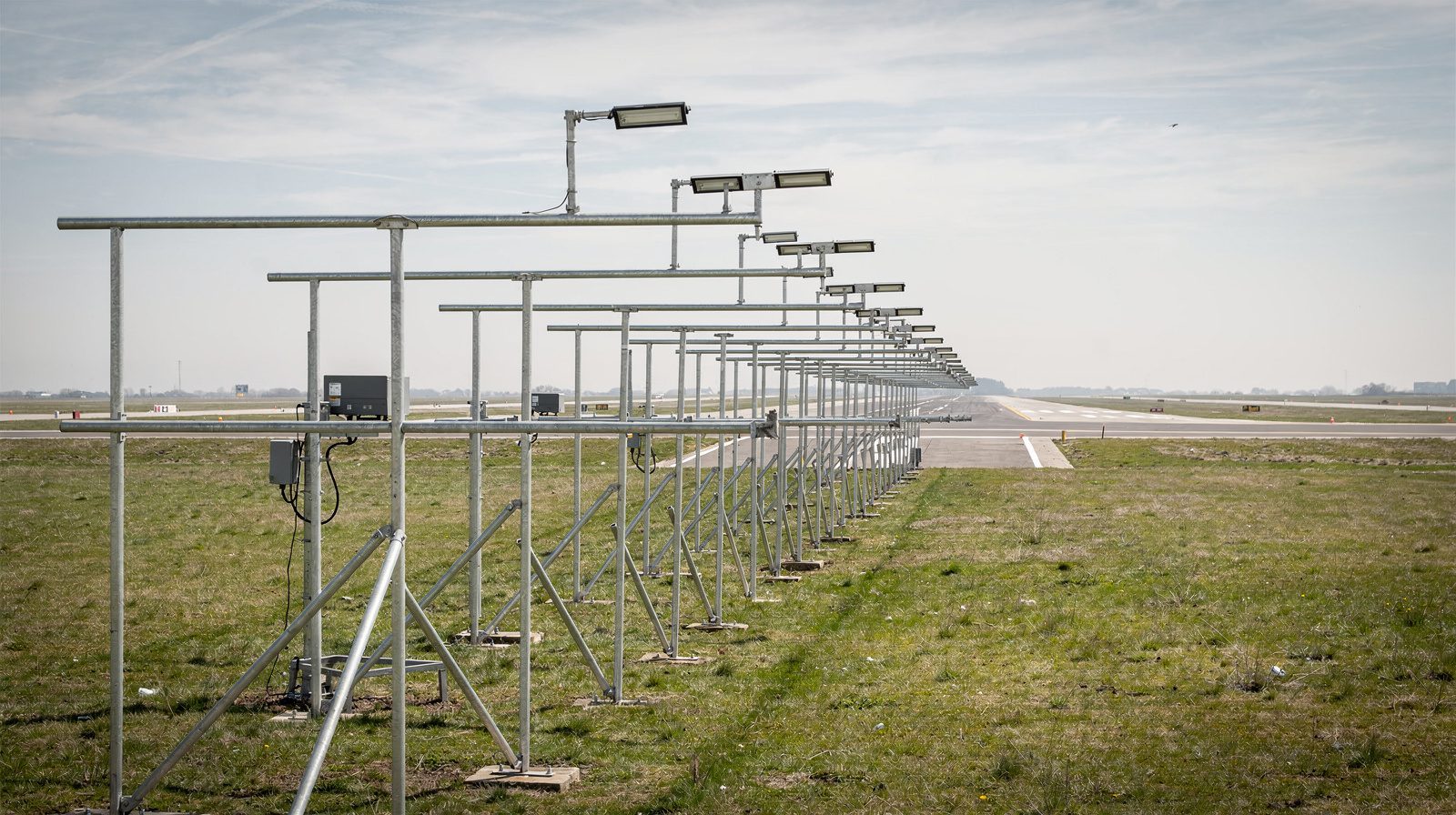
Fixtures come in two forms. Elevated units stand on a frangible stem beside the pavement. Inset units sit flush in the pavement wherever an elevated one would be struck, at intersections and where the paved width is used to the edge, and are built to be rolled over by aircraft wheels.
HIRL, MIRL and LIRL
The three acronyms are the FAA’s classes of runway edge lighting. FAA AIM 2-1-4 classifies them by the intensity the system can produce, and AC 150/5340-30J chooses the class by runway type.
- HIRL , high intensity runway lights, is installed on precision instrument runways. It has five brightness steps, from 0.15 percent to full output.
- MIRL , medium intensity runway lights, is installed on visual or non-precision instrument runways. On a series circuit it has three brightness steps.
- LIRL , low intensity runway lights, is installed on visual runways at small airports and normally has one setting.
The step count follows from the class and does not define it. The elevated fixtures in AC 150/5345-46F are typed by runway rather than by class name: L-862 for precision instrument runways, L-861 for non-precision instrument runways and L-860 for visual runways.
The EU and ICAO do not use the three names. CS-ADR-DSN and Annex 14 specify the light itself: an isocandela diagram for edge lights on a precision approach runway, chosen by runway width, and a minimum intensity for runway edge lights in general. Every other type of light, from the threshold to the approach centre line, has its own specification. Authorities that follow CS-ADR-DSN still buy fixtures sold under the FAA class names, so the acronyms appear in tenders and maintenance records worldwide.
Specification
The rows below are what a runway edge light and its installation are specified to, each value with its unit and the clause it comes from.
What a runway edge light is specified to
Installation geometry, colour, photometrics and serviceability limits for the fixture.
Any runway used at night, any precision approach runway by day or night, and a runway for take-off below an RVR of about 800 m by day.
Two parallel rows along the full runway length, equidistant from the centre line, with opposite lights on lines at right angles to the axis.
Uniform spacing, closer on instrument runways. At a runway intersection lights may be spaced irregularly or omitted if guidance stays adequate.
On the edge of the area declared as runway, or a short distance outside it.
Fixed lights showing variable white over the usable length.
The section at the far end from the start of the take-off run shows yellow.
Lights before a displaced threshold show red toward the approach. The FAA fixture shows white outbound for take-off.
White, yellow and red inside the colour boundaries for aeronautical ground lights.
Light shown at every azimuth a pilot needs landing or taking off in either direction, and at all azimuths where the lights give circling guidance.
Shown up to 15° above the horizontal at an intensity adequate for the visibility and ambient light. The minimum below is for runway edge lights, and every other type of light has its own.
Edge lights on a precision approach runway follow the isocandela diagram for the runway width. The values are printed on the diagram itself.
The main beam is aimed inward toward the centre line, as given in the notes to the isocandela diagrams.
The row dims in steps to suit visibility and ambient light. The FAA class follows from the intensity the system can produce, not from the step count.
Low enough to keep clear of propellers and the engine pods of jet aircraft.
An elevated light and its stem break away when struck by an aircraft.
An inset light withstands aircraft wheels rolling over it and does not overheat a tyre resting on it.
A light is unserviceable once its main beam average intensity falls below half the specified value, or half the design value where that is higher, or when its filter is missing or damaged or its colour is wrong.
Share of lights serviceable, set separately for each system. No unserviceable light next to another unless the spacing is much closer than required.
Share of lights serviceable in each system during CAT II or III operations. No two adjacent lights out, except two in a barrette or crossbar.
Runways used for take-off, set by runway visual range. No unserviceable light next to another.
Serviceability and inspection
A runway edge light that is lit is not necessarily serviceable. Under ADR.OPS.C.015 a light is unserviceable once its main beam average intensity falls below half the specified value, which happens long before the eye notices anything, as lenses haze, filters fade and stems drift out of alignment. The serviceability limits are then set per system and per type of operation, not for the edge lights alone. On a CAT I runway at least 85 percent of the lights must be serviceable in each of the approach, threshold, edge and runway end systems. For CAT II and III the edge lights must reach 95 percent, alongside separate figures for the approach lighting, the centre line, the touchdown zone and the runway end, and an unserviceable light must not sit next to another one.
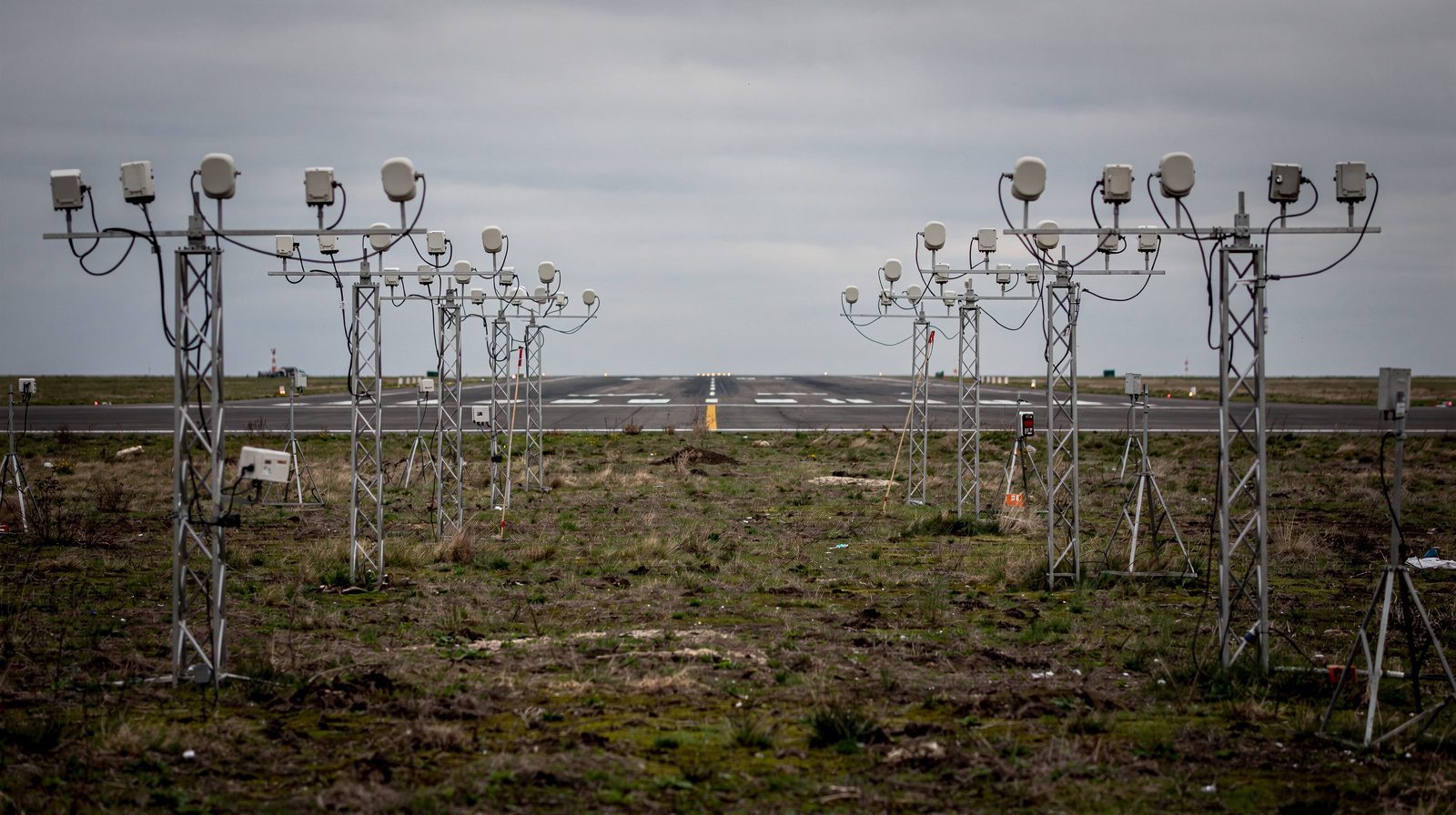
Proving that needs a photometric measurement of every unit, not a walk down the row. TarmacView’s runway edge lights inspection flies the rows at each intensity step and reports intensity, colour, beam shape and position per unit against the values in the table above, with a ranked list of the units to attend to.
Related terms
Edge light is the general term covering runway, taxiway and apron edges. Taxiway edge lights are blue and spaced by taxiway geometry rather than a fixed interval. Runway centreline lights, touchdown zone lights and threshold lights complete the runway lighting system the edge lights belong to.
Frequently Asked Questions
- What are HIRL, MIRL and LIRL?
- They are the FAA's classes of runway edge lighting, set by the intensity the system can produce. AC 150/5340-30J puts HIRL (high intensity runway lights) on precision instrument runways, MIRL (medium intensity) on visual or non-precision instrument runways and LIRL (low intensity) on visual runways at small airports. HIRL and MIRL have variable intensity control and LIRL normally has one setting. CS-ADR-DSN and ICAO Annex 14 do not use the names.
- How far apart are runway edge lights and how far from the edge?
- CS-ADR-DSN in the EU and ICAO Annex 14 set uniform spacing of not more than 60 metres on an instrument runway and not more than 100 metres on a non-instrument runway, with the lights on the runway edge or not more than 3 metres outside it. The FAA equivalent in AC 150/5340-30 is a maximum of 200 feet between lights, placed 2 to 10 feet from the edge of the full-strength pavement.
- What do the colours of runway edge lights mean?
- Along most of the runway the lights are white and mark the usable surface. The section nearest the far end can be yellow as a caution that little runway remains. CS-ADR-DSN and ICAO Annex 14 set that section at 600 metres or one third of the runway length, whichever is less. The FAA rule, for instrument runways, is the last 2,000 feet or half the runway length, whichever is less. Where a threshold is displaced, the lights before it show red toward the approach. Red runway end lights mark the end of the usable surface.
- How do runway edge lights differ from threshold, end and centreline lights?
- Edge lights are white or yellow and run in two rows along the runway sides. Threshold lights are green and mark where the landing surface begins. Runway end lights are red and mark where it ends. Runway centreline lights are inset white lights along the runway axis that turn alternating red and white and then all red over the last 900 metres. Taxiway edge lights are blue.
References
- icao-annex-14-vol-1
- Annex 14 to the Convention on International Civil Aviation, Volume I, Aerodrome Design and Operations ICAO
- faa-ac-150-5340-30
- AC 150/5340-30J, Design and Installation Details for Airport Visual Aids FAA
- faa-ac-150-5345-46
- AC 150/5345-46F, Specification for Runway and Taxiway Light Fixtures FAA
- faa-aim-2-1-4
- Aeronautical Information Manual, Chapter 2 Section 1, paragraph 2-1-4 Runway Edge Light Systems FAA
- easa-ear-aerodromes
- Easy Access Rules for Aerodromes (Regulation (EU) No 139/2014), including CS-ADR-DSN Issue 7 EASA
- uk-caa-cap-168
- CAP 168, Licensing of Aerodromes, Edition 13 UK Civil Aviation Authority
- nato-stanag-3316
- STANAG 3316, Airfield Lighting NATO Standardization Office
This is a reference entry. TarmacView provides drone inspection services and doesn't sell the equipment or materials described in this glossary.