Aerodrome Visual Aids: What an Inspection Must Cover
How airfield lighting is controlled, what aerodrome visual aids are, what day marking means, and what an inspection must cover for every class of aid it covers.
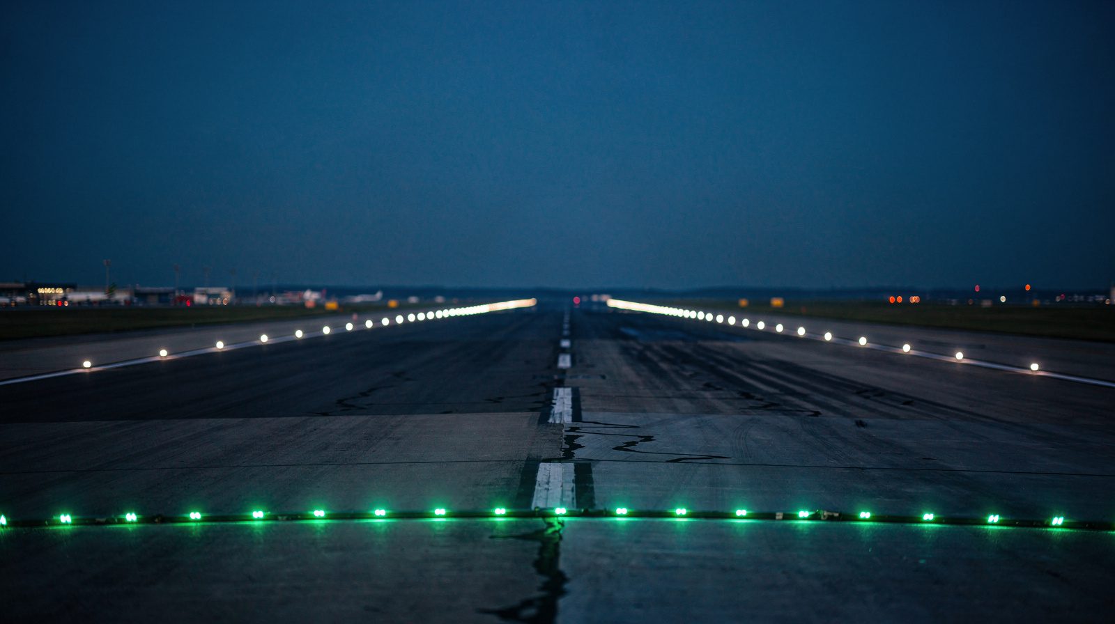 EDGE LIGHTS · THRESHOLD · DUSK
Visual aids is a wider category than lighting
Aerodrome visual aids are the indicators, markings, lights, signs and markers that guide a pilot, and Annex 14 adds aids for obstacles and restricted areas. Day marking is a painted marking, with no separate Annex term. In the FAA system, lights are normally controlled from the control tower and the lighting vault, and by pilot radio click at some airports.
Ask an airfield team what its visual aids inspection covers and the answer is usually a list of lights. That is not what the standard means by the term, and the gap matters, because the classes nobody counts as visual aids are the classes nobody schedules an inspection for.
Annex 14 Volume I spreads visual aids across three chapters. Chapter 5, “Visual aids for navigation”, has five parts: indicators and signalling devices, markings, lights, signs, and markers. Chapter 6 covers visual aids for denoting obstacles. Chapter 7 covers visual aids for denoting restricted use areas. Lighting is one part of one chapter.
A programme that measures only the lights covers one class out of seven. The table lists what an inspection has to establish for each.
| Class | Annex 14 Vol I | Typical members | What an inspection has to establish |
|---|---|---|---|
| Indicators and signalling devices | 5.1 | Wind direction indicator, landing direction indicator, signalling lamp | Presence, and illumination of at least one wind indicator where the aerodrome is used at night |
| Markings | 5.2 | Designation, centre line, threshold, aiming point, holding position | Presence, geometry against the design, colour and conspicuity against the surface |
| Lights | 5.3 | Approach, edge, threshold, end, centre line, touchdown zone, taxiway | Main beam intensity, beam spread, aiming, colour, response to a commanded intensity setting |
| Signs | 5.4 | Mandatory instruction, information, runway distance remaining | Legibility, correct inscription, installed height and offset, frangibility |
| Markers | 5.5 | Unpaved runway edge, stopway edge, taxiway edge, boundary | Continuity of delineation, frangibility of the mounting |
| Obstacle marking and lighting | Ch 6 | Painted patterns and obstacle lights on structures | Which objects are marked or lit, and whether the lights work |
| Restricted use area aids | Ch 7 | Closed runway markings, unserviceability markers | Presence and placement for as long as the restriction lasts |
How airfield lighting is controlled
Control has two layers. The first is the intensity control. Annex 14 requires a suitable intensity control wherever a high-intensity lighting system is provided. It also requires separate intensity controls, or another suitable method, so that the approach lights, runway edge, threshold, end, centre line and touchdown zone lights and the taxiway centre line lights can run at compatible intensities.
The second layer is the control point. The FAA describes the control system as the panels, relays and circuits that switch lighting circuits on and off and select lamp brightness. It normally provides control of any one system at two points only: the control tower and the lighting vault that powers the system.
Some airports add radio control. A pilot controlled lighting receiver lets a pilot key the microphone to switch the lights on. The FAA AIM describes a three-step control that responds to 7, 5 or 3 clicks and keeps the lights on for 15 minutes from the last activation. For the wider glossary entry see control system .
Annex 14 adds two rules that matter to an inspector. Where a runway on a standard taxi-route has both runway and taxiway lighting, the two systems are interlocked so that they cannot operate at the same time. And a monitoring system should indicate the operational status of the lighting, within two seconds for a stop bar at a runway-holding position and within five seconds for every other type of visual aid.
Four classes, four different questions
The classes look like one domain and behave like four. What an inspector has to establish differs in each, and so does the instrument that can establish it.
A marking is a geometry and contrast problem
A ground marking is assessed for three things: that it is there, that it is the right shape in the right place, and that it can be seen against the surface it is painted on.
Conspicuity is relative. Annex 14 fixes the colours: runway markings white, taxiway, turn pad and aircraft stand markings yellow, apron safety lines a conspicuous colour that contrasts with the stand markings. It then notes that on light-coloured runway surfaces the conspicuity of white markings can be improved by outlining them in black. A marking can be correct in every dimension and still be hard to see against its surface.
What day marking means
Day marking is the everyday name for a painted marking that a pilot or driver reads in daylight. Annex 14 does not define it as a separate type. It defines one thing, a marking, and the same marking serves by day and by night. For airfield-wide marking inspection see airfield marking inspection .
A light is a photometric problem
A light is assessed for how much light it puts into a specific direction, over what angular extent, in what colour, and whether it follows the intensity setting it was commanded to follow.
A sign is a legibility and frangibility problem
Signs carry two requirements that have nothing to do with one another. The inscription has to be readable at the range a crew reads it from, which is a function of legend height, contrast and internal illumination. The structure has to break on contact. Annex 14 requires signs to be frangible and, where they sit near a runway or taxiway, low enough to preserve clearance for propellers and the engine pods of jet aircraft. Its Table 5-5 fixes the geometry: at a code 3 or 4 aerodrome a 400 mm legend on a face of at least 600 mm, installed no higher than 1,100 mm, sited 11 to 21 m from the defined taxiway pavement edge or 8 to 15 m from the defined runway pavement edge. On the movement area, red is reserved for mandatory instruction signs and nothing else.
A marker is a delineation and frangibility problem
Markers do the job of lights where there are no lights, along unpaved runway edges, stopway edges, snow-covered runway edges, taxiway edges and boundaries. Annex 14 requires markers to be frangible and low enough to clear propellers and engine pods. It recommends that where runway lights are provided the markers be incorporated in the light fixtures. The inspection questions are whether the delineation is continuous and whether the mounting will let go.
Why serviceability is defined by measured intensity
Annex 14 defines the failure precisely. A light is deemed unserviceable when its main beam average intensity is less than 50 per cent of the value specified in the relevant Appendix 2 figure, and where a unit was designed above that value, the 50 per cent is taken against the design value.
Main beam average intensity is a procedure, not an impression. Appendix 2 defines it as the arithmetic average of the intensities measured at grid points lying within and on the perimeter of the ellipse that defines the main beam. Two further constraints sit on top of it. Within that ellipse, the maximum intensity must not be more than three times the minimum. And the unit has to be installed so that its main beam is aligned within one-half degree of the specified requirement.
A definition written as an average over a grid and an aiming tolerance of half a degree cannot be applied by looking at a row. That is the case for photometric testing as an activity separate from a walk-down. Annex 14 itself asks for in-field measurement of intensity, beam spread and orientation in its maintenance recommendations for precision approach runways of category II or III.
The classes are judged against each other, not alone
A serviceability decision is rarely about one aid. Annex 14 requires that the intensity of runway lighting be adequate for the minimum visibility and ambient light the runway is intended to be used in, and compatible with the nearest section of the approach lighting system. The stated reason is that an abrupt change in intensity can give a pilot the false impression that the visibility is changing during the approach.
Appendix 2 makes that relationship numeric. The average intensity within the main beam of a new light is set as a ratio of the minimum average intensity of a new runway edge light, and the ratios also define the maximum allowed.
| Element | Ratio to a new runway edge light | Colour |
|---|---|---|
| Approach centre line and crossbars | 2.0 to 3.0 | White |
| Approach side row | 0.5 to 1.0 | Red |
| Threshold | 1.0 to 1.5 | Green |
| Threshold wing bar | 1.0 to 1.5 | Green |
| Touchdown zone | 0.5 to 1.0 | White |
| Runway centre line, 30 m spacing | 0.5 to 1.0 | White |
| Runway centre line, 15 m spacing | 0.5 to 1.0 for CAT III, 0.25 to 0.5 for CAT I and II | White |
| Runway end | 0.25 to 0.5 | Red |
| Runway edge | 1.0 to 1.5 | White |
Annex 14 says the runway lighting system has to be considered as a whole, so that the relative light intensities are suitably matched and maintained over time. It also observes that in dusk or poor visibility by day, lighting can be more effective than marking. The aids work as one system, and an inspection that scores each unit alone does not check that.
Routine serviceability and periodic measurement are not the same job
Annex 14 requires a preventive maintenance system for visual aids that ensures lighting and marking system reliability. For a precision approach runway category II or III it then recommends what that system should contain: visual inspection and in-field measurement of the intensity, beam spread and orientation of the approach and runway lights, control and measurement of the electrical characteristics of every circuit, and confirmation that the light intensity settings used by air traffic control actually do what they are commanded to do.
The measurement should cover all lights as far as practicable, using a mobile measuring unit of sufficient accuracy to analyse individual lights. Its frequency should follow traffic density, the local pollution level, the reliability of the installed equipment and the trend in previous results, and in any event should not be less than twice a year for in-pavement lights and not less than once a year for the others. That is the recommendation for CAT II and III. For other runways the standard sets no measurement interval.
Automatic monitoring answers a different question. Annex 14 recommends a system that indicates the operational status of the lighting, which is a statement about whether a light is on. The measurement recommendation in 10.5.3 is about how much light it delivers.
Two of those classes carry more detail than a map should. The serviceability percentages, the adjacency rule and the pattern arithmetic are in approach lighting system inspection . The colour zones, spacing and degradation modes of a row are in runway edge light inspection .
Runway edge light inspection checklist
The Annex 14 requirements below give a checklist for the edge light row. Check each item against the aerodrome’s own design and manual.
- Two parallel rows along the full length of the runway, equidistant from the centre line and within 3 m of the runway edge.
- Uniform spacing of not more than 60 m on an instrument runway and not more than 100 m on a non-instrument runway.
- Fixed lights showing variable white. Red between the runway start and a displaced threshold. Yellow is allowed on the last 600 m, or the last third of the runway if that is shorter, at the far end from the take-off start.
- Intensity of at least 50 cd up to 15 degrees above the horizontal, or at least 25 cd at an aerodrome without extraneous lighting.
- Elevated lights frangible and low enough to preserve clearance for propellers and engine pods.
- Main beam average intensity at or above 50 per cent of the Appendix 2 value, with the maximum no more than three times the minimum in the main beam, and aiming within one-half degree.
- A preventive maintenance system in place, and the circuits and intensity settings tested as in 10.5.3 where the runway is CAT II or III.
For the serviceability limits that follow from this, see runway light serviceability limits .
Where a drone fits, and what still needs a ground crew
TarmacView offers drone inspection of airfield lighting. It does not offer a drone inspection of markings, signs, markers or obstacle marking yet, and those are in development.
| Class | Drone inspection today | Ground work |
|---|---|---|
| Lights | Intensity, colour, beam shape and position measured for each unit of a runway edge light row | Fixture adjustment, relamping, and measurement of circuit electrical characteristics |
| Markings | Not offered yet | Repaint, cleaning, rubber removal |
| Signs | Not offered yet | Legend, illumination and installation checks |
| Markers | Not offered yet | Physical check of the mounting |
| Obstacle marking and lighting | Not offered yet | Access for repainting and lamp change |
Frangibility is a mechanical property of a sign, marker or light mounting, so it is a physical check. The electrical characteristics of a circuit are a measurement taken on the circuit. A useful inspection programme runs the aerial and the ground work and does not pretend either one covers the other.
Can drone measurements serve as audit evidence
Whether an auditor accepts a drone measurement is the regulator’s decision, and Annex 14 does not mention drones. What it does ask for is in-field measurement by a mobile unit of sufficient accuracy to analyse individual lights. A measurement is worth more to an auditor when it is a number against a fixture, taken with a known method, than when it is a statement that the lights looked fine. See what a regulator actually accepts as evidence and drone survey vs flight inspection .
The short version
Visual aids is a regulatory category with seven parts, and only one of them is usually measured. Markings are settled by geometry and contrast. Signs and markers are settled by legibility and by whether the mounting breaks. Lights are settled by photometry, against a definition of failure written as an average intensity over a grid and an aiming tolerance of half a degree. And none of the classes is judged alone, because the standard specifies the elements as ratios to each other and the crew reads them as one picture.
An inspection that covers the lights and nothing else is not covering the visual aids.
Frequently Asked Questions
- How is airfield lighting controlled?
- Airfield lighting is controlled from panels that switch circuits and select lamp brightness. The FAA says control of one system is normally at two points only, the control tower and the lighting vault. Annex 14 requires intensity controls so that approach, runway and taxiway lights run at compatible intensities. Some airports add pilot radio control.
- What are visual aids at an aerodrome?
- Visual aids are the indicators, markings, lights, signs and markers that guide a pilot on and near the aerodrome. Annex 14 Chapter 5 covers these five parts. Chapter 6 covers aids for denoting obstacles and Chapter 7 covers aids for denoting restricted use areas.
- What is day marking?
- Day marking is the everyday name for a painted marking that is read in daylight. Annex 14 does not define it as a separate type. It defines a marking, and runway markings are white while taxiway, turn pad and aircraft stand markings are yellow.
- What does a runway edge light inspection checklist cover?
- A runway edge light checklist covers position, spacing, colour, intensity, frangibility and aiming. Annex 14 sets spacing of not more than 60 m on an instrument runway, white light with allowed red and yellow sections, and a light is unserviceable below 50 per cent of its specified main beam average intensity.
- Can drone measurements be used as compliance evidence in an aerodrome audit?
- That is the regulator's decision, and Annex 14 does not mention drones. It asks for in-field measurement of intensity, beam spread and orientation with a unit of sufficient accuracy to analyse individual lights. A measured number per fixture, with a known method, is the kind of record an auditor can check.
References
- icao-annex-14-vol1
- ICAO Annex 14, Volume I, Aerodrome Design and Operations, 9th edition (July 2022, consolidated copy) ICAO, copy hosted by the Swiss FOCA
- faa-ac-150-5340-30j
- AC 150/5340-30J, Design and Installation Details for Airport Visual Aids FAA
Founded by flight-inspection veterans who spent decades measuring PAPI lights for aviation authorities across Europe.
Learn more
Related terms
03 TERMSVisual Aids
What visual aids are: indicators, markings, lights, signs and markers. The groups in ICAO, EASA and FAA documents, the colours, obstacle marking and who keeps them working.
Aviation Light
An aviation light is a light used in aviation, on the ground at an aerodrome or on an aircraft. The light groups, their colours, obstacle lights and serviceability.
Airfield Lighting
Airfield lighting is the set of aeronautical ground lights at an aerodrome. It covers light types and colours, FAA systems, obstacle lights, brightness, power, temporary lighting, serviceability, and EU, US and UK rules.
Further reading
03 ARTICLES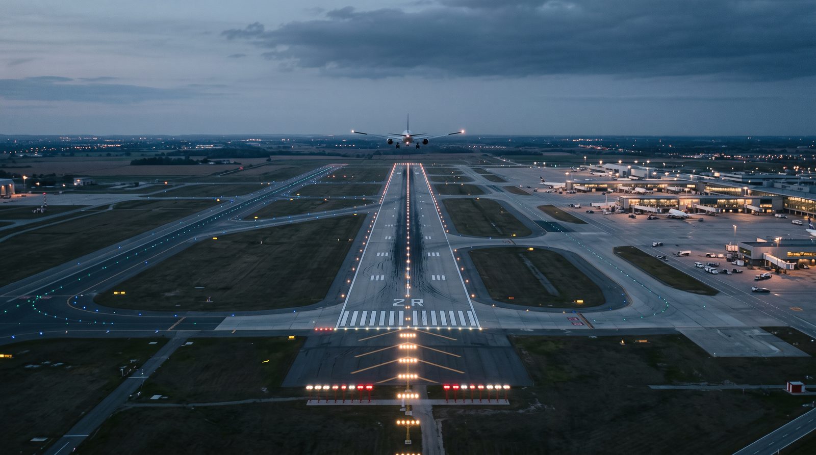
ICAO Annex 14: Aerodrome Visual Aids and Their Maintenance
What ICAO Annex 14 Volume I says about aerodrome lighting: the visual aids in Chapter 5, power and monitoring in Chapter 8, and serviceability in…
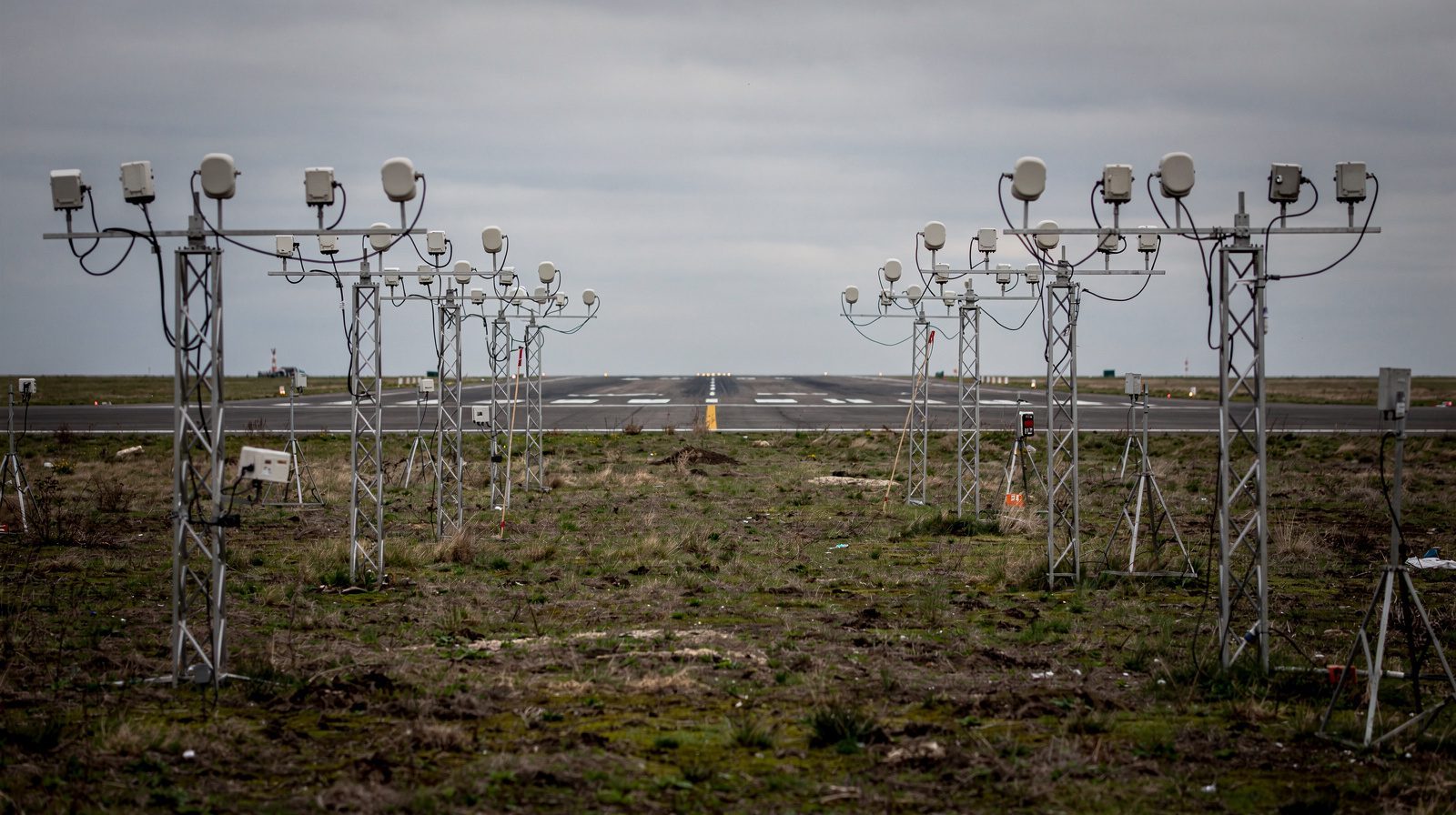
Approach Lighting System Inspection
What an approach lighting system does for the crew, what Annex 14 asks of it in service, and why 900 metres of array off the airport is hard to…

Runway Edge Light Inspection: What ICAO Requires and How It Is Measured
What ICAO Annex 14 requires of runway edge lights, what it leaves open, and how intensity, colour and coverage are actually measured in the field.