Airfield Lighting Control: Intensity Steps and Standby Power
How intensity control of airfield lights works: brightness steps set by a constant current regulator, who selects them, the FAA values and secondary power.
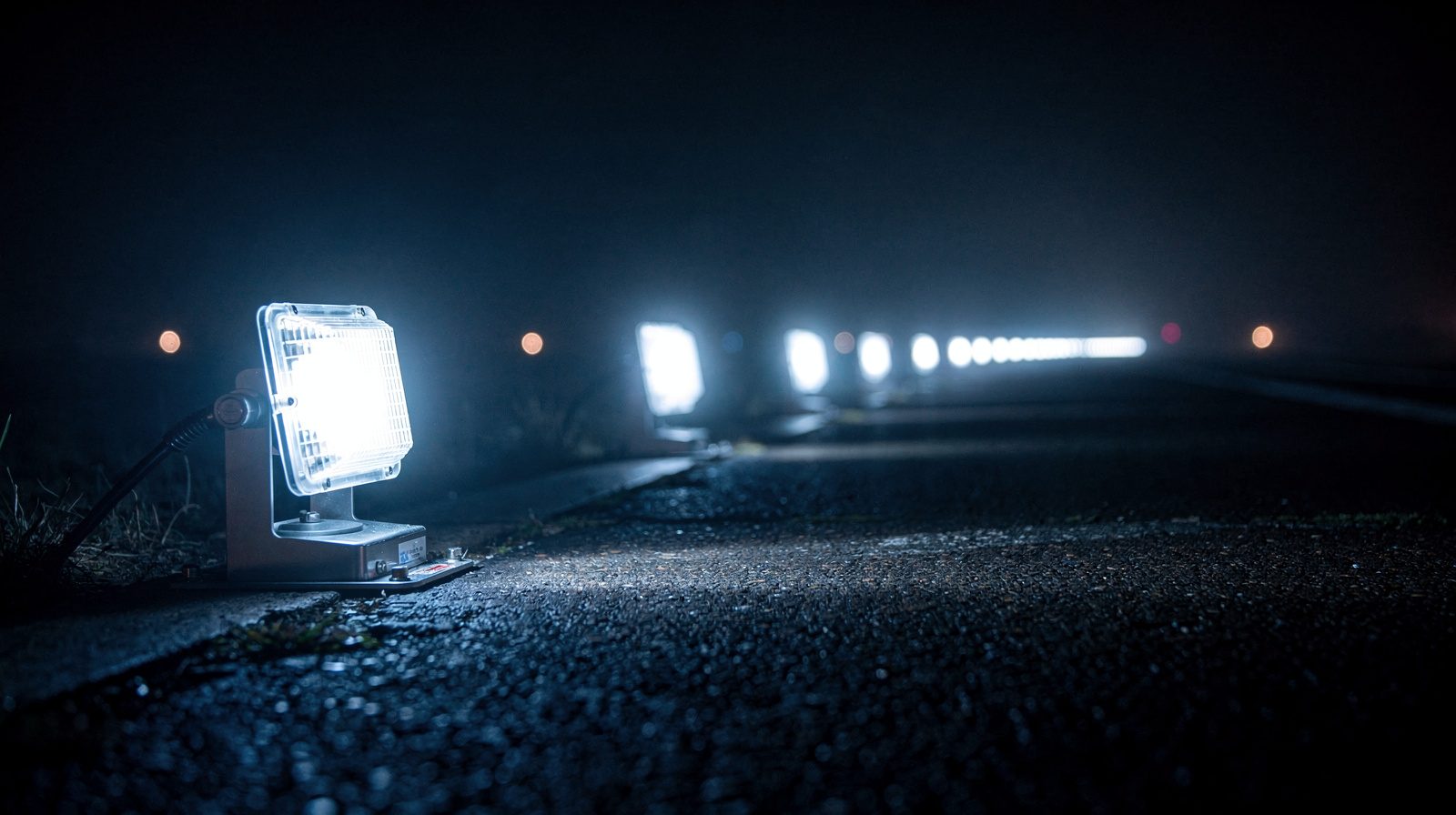 INTENSITY STEP · GROUND FOG · NIGHT
Intensity control sets how bright a group of airfield lights burns. On a series circuit, a constant current regulator (CCR) changes the lamp current, and each current value is one brightness step, given as a percentage of full brightness. A high intensity runway edge circuit has five steps and a medium intensity circuit has three.
The measurement without the step is not evidence
A photometric result alone is a number. A photometric result with the intensity control step recorded is a claim. The difference matters for airfield inspection.
When you measure a runway light, you measure it at a particular step on the constant-current regulator. Step 1 is not the same light as Step 5, and a report that does not name the step hides the most material fact about what was tested.
What intensity levels and intensity steps are
An intensity level is a preset brightness setting. An intensity step is the same preset on a circuit that has several, counted from the lowest. FAA AC 150/5340-30J defines each step as a percentage of the full brightness of the lamp.
The number of steps depends on the system. A high intensity runway light (HIRL) circuit has five. A medium intensity circuit (MIRL or MITL) has three. A low intensity runway light (LIRL) has one. The AIM says HIRL and MIRL have variable intensity controls, and LIRL normally has one setting.
High, medium, low and full intensity
High, medium and low intensity are classes of runway edge light. The AIM names them for the brightness they can produce. Full intensity is not a class. It is a setting, the highest step of a circuit. A HIRL circuit at full intensity runs at step 5, 100 percent. The same circuit at step 1 is still a high intensity light, running at 0.15 percent.
How a regulator sets the step
Series-powered airport lighting circuits are powered by CCRs, and the CCRs provide the number of brightness steps. A constant-current regulator (CCR) holds the current of the circuit at the value for the selected step. On a 6.6 ampere circuit, the highest step runs the lamps at 6.6 A.
Each lamp sits behind an isolation transformer, rated 6.6/6.6 amperes in the AC. A series circuit has one current path, so the transformer lets one lamp fail or be disconnected without breaking the loop for the others.
The steps are not equal increments. In the HIRL table, the step below full brightness is 25 percent, and the lowest step is 0.15 percent. A step is a defined current and a defined percentage, so it cannot be swapped for a rounded figure.
| Intensity step | HIRL brightness | HIRL lamp current | MIRL brightness | MIRL lamp current |
|---|---|---|---|---|
| Step 5 | 100% | 6.6 A | ||
| Step 4 | 25% | 5.2 A | ||
| Step 3 | 5% | 4.1 A | 100% | 6.6 A |
| Step 2 | 1.2% | 3.4 A | 30% | 5.5 A |
| Step 1 | 0.15% | 2.8 A | 10% | 4.8 A |
Source: AC 150/5340-30J, paragraph 2.6.4. The MIRL values are for a series circuit with an L-828 or L-829 regulator. These are FAA values. Annex 14 and CS-ADR-DSN specify each type of light in its own figure.
Who selects the step
The control tower operates the approach lights and the runway lighting, and a pilot may ask for a different intensity. At airports with FAA-approved radio control, the pilot keys the aircraft microphone instead. The control has three steps. Seven clicks within 5 seconds select the highest intensity available, five select a medium or lower intensity and three select the lowest. The lights stay on for 15 minutes from the latest activation.
For a runway without approach lights, the AIM table lists HIRL at step 1 or 2 for low, step 3 for medium and step 5 for high. Some systems follow a photocell, with low intensity for night and high intensity for day.
ICAO Annex 14 gives the reason for the choice. The right setting depends on both the background brightness and the visibility, and too much intensity dazzles the pilot.
Why the step is the critical record
Each type of light has its own specification, and a measured value only means something against the step it was measured at. A result with no step is ambiguous. The same result with the step named is evidence you can compare with what applies at that step.
Record the step in the data, not in a separate note. If a light reads in tolerance at Step 3 but not at Step 5, say so. A chart of results across several steps shows how the light performs across the range, and a lamp that fails only at full intensity tells you it is marginal where full intensity is needed.
TarmacView reports the intensity of each unit relative to its neighbours and to the commanded dimming step. Absolute intensity in candela needs a calibrated photometer.
What the monitoring system sees and does not see
A monitoring system on a lighting circuit reports electrical status. When a lamp opens, the system raises a lamp failure indication. Annex 14 recommends a monitoring system to indicate the operational status of the lights, and requires automatic monitoring where the lights are used for aircraft control.
An electrical alarm is not a measurement of brightness. A lamp that still lights is not a failed lamp, even if its output has drifted. A photometric test measures the light itself. A maintenance window where the monitoring system reports all nominal means nothing has failed. It does not show that every light is in tolerance.
Secondary power and the switch-over requirement
Annex 14 recommends that the connections to facilities that need secondary power are arranged so they connect automatically when the primary source fails. For a precision approach runway, and for a runway meant for take-off below 800 m runway visual range, a secondary power supply that meets Table 8-1 is a requirement, a shall.
Table 8-1 sets the maximum switch-over time. Annex 14 defines it as the time for the actual intensity of a light, measured in a given direction, to fall from 50 percent and recover to 50 percent during a changeover, when the light runs at 25 percent or above.
| Runway | Lights | Maximum switch-over time |
|---|---|---|
| Non-precision approach | Approach lighting, runway edge, threshold, end | 15 seconds |
| Precision approach category I | Approach lighting, runway edge, threshold, end | 15 seconds |
| Precision approach category II or III | Inner 300 m of the approach lights, threshold, end, centre line, touchdown zone, stop bars | 1 second |
| Precision approach category II or III | Other approach lights, runway edge | 15 seconds |
How an inspection should record configuration
When you measure a light, document the intensity step. When you measure a system, record which step you used, the weather, the time of day and any adjustment the airfield team made during the work.
If you measure the same light at several steps, list all of them in a table. If maintenance adjusts the light and you re-measure at the same step, the re-measurement shows whether the adjustment worked. The strongest evidence is specific: the light was measured at Step 5, read below specification before adjustment and within tolerance after it.
This is how we run an approach lighting inspection , reading each unit at the configured step and recording where adjustments are needed.
Why this matters for your inspection report
A photometric result is evidence of the system state on a specific day at a specific step. Name the step and note the conditions. How that evidence turns into action is covered in when runway lights drift out of tolerance , and the full procedure is in the photometric measurement guide .
If you are checking approach lighting, the report should say which step the array ran at, whether every unit was read at the same step and which step applied to your pass-or-fail decision. A strong routine records the step alongside the result, every time. It is the difference between evidence and a data point.
Frequently Asked Questions
- How does intensity control of airfield lights work?
- A constant current regulator (CCR) sets the current in a series lighting circuit, and each current value gives one brightness step. FAA AC 150/5340-30J defines each step as a percentage of the full brightness of the lamp. The control tower, a pilot radio call or a photocell selects the step.
- How many intensity steps do runway lights have?
- It depends on the system. In FAA AC 150/5340-30J a high intensity runway edge light (HIRL) circuit has five steps, a medium intensity circuit has three and a low intensity runway light (LIRL) has one. Other systems, such as approach lights, may have two or three.
- What is the difference between high, full and low intensity airfield lights?
- High, medium and low intensity are classes of runway edge light, named for the brightness they can produce (FAA AIM 2-1-4). Full intensity is a setting, the highest step of a circuit. A HIRL circuit can run at full intensity, which is step 5, or at a lower step.
- How does a pilot control airfield lighting intensity?
- At airports with FAA-approved radio control, the pilot keys the aircraft microphone. Seven clicks within 5 seconds select the highest intensity available, five select a medium or lower intensity and three select the lowest. The lights stay on for 15 minutes from the last activation.
- How fast must secondary power take over when the main supply fails?
- ICAO Annex 14 Table 8-1 sets a maximum switch-over time by runway type. It is 15 seconds for most lights on non-precision and category I runways. On category II and III runways it is 1 second for the inner 300 m of the approach lights, the threshold, the runway end, the centre line and the touchdown zone.
References
- faa-ac-150-5340-30j
- AC 150/5340-30J, Design and Installation Details for Airport Visual Aids FAA
- icao-annex-14-vol-i
- ICAO Annex 14, Volume I, Aerodrome Design and Operations, 9th edition (July 2022) ICAO
Founded by flight-inspection veterans who spent decades measuring PAPI lights for aviation authorities across Europe.
Learn more
Related terms
03 TERMSIntensity Step
An intensity step is a preset brightness level of an airfield light, set as a percentage of full brightness. FAA step values and lamp currents, 3-step and 5-step CCRs, and how inspection checks them.
Full Intensity – Maximum Light Output Setting
Full intensity is the highest brightness step of an airfield lighting circuit. The brightness steps and lamp currents, when ATC uses full intensity, how a pilot selects it, and how to check output.
Intensity Level
An intensity level is a preset brightness setting of an airfield light. How many levels each light has, what low, medium and high mean, who selects them, and what an inspection checks.
Further reading
03 ARTICLES
How Often Does Airfield Lighting Need Photometric Testing?
How often airfield lighting is photometrically tested: no Part 139 interval, a twice-yearly floor on precision runways, monthly FAA tables and what a…
LED Airfield Lighting: What Changes for Inspection
How LED airfield lighting changes photometric inspection: LEDs fade instead of burning out, colour can drift and ice can stay, so each light needs…
Runway Edge Light Inspection: What ICAO Requires and How It Is Measured
What ICAO Annex 14 requires of runway edge lights, what it leaves open, and how intensity, colour and coverage are actually measured in the field.