FAA AC 150/5345-46: Runway and Taxiway Light Fixture Specification
What FAA AC 150/5345-46F requires of runway and taxiway light fixtures: types, photometric minimums and what an installed light is compared with in the field.
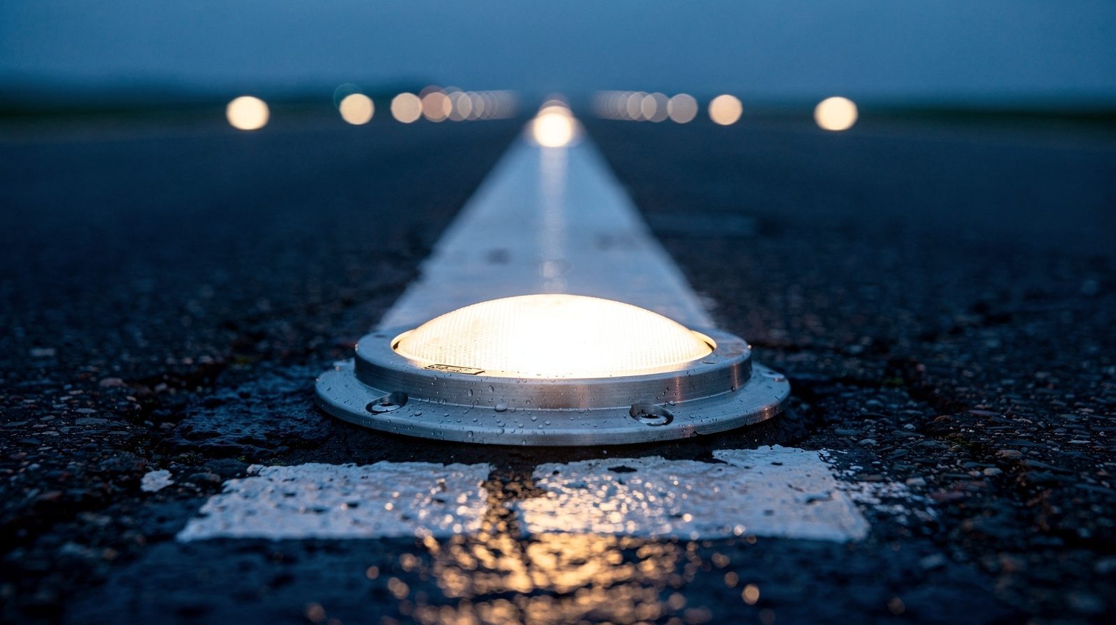
- 01 The circular is a manufacturer-facing product specification. Chapter 4 tests a fixture design with random production-run lamps, and the text has no procedure for measuring a light already installed.
- 02 Tables 3-1 to 3-3 give each type a minimum average intensity over a main beam, at least half of it at every point inside, and at least 10 percent on the outer ellipse. The average may not exceed three times the figure.
- 03 Paragraph 4 makes the circular mandatory on projects funded by federal grants such as AIP and on PFC-funded projects, and an acceptable means of meeting 14 CFR 139.311. For other operators it is recommended.
- 04 AC 150/5340-26C compares an installed light with the minimum required for its fixture type and flags output below 70 percent. ICAO Annex 14 paragraph 10.5.1 sets the unserviceable line at 50 percent of its own figures.
- 05 A drone survey reports output relative to neighbouring lights and to the commanded step. Deciding the 70 percent test needs absolute candela from a calibrated photometer.
On this page · 10 sections
A runway edge light, also called a side light, is one of two rows of lights marking the runway sides. FAA AC 150/5340-30J limits spacing between units to 200 feet (61 m). ICAO Annex 14 allows at most 60 m on an instrument runway and 100 m on a non-instrument runway. AC 150/5345-46F specifies the fixture.
The FAA keeps its specification for runway and taxiway light fixtures in one advisory circular. AC 150/5345-46F, Specification for Runway, Taxiway, Heliport, and Vertiport Light Fixtures, is dated 30 September 2024 and was initiated by AAS-100, the FAA Airport Engineering Division. It cancels AC 150/5345-46E and runs to five chapters. It names each fixture type by its L-number, defines the beam each must produce and sets out the tests a manufacturer must pass. The circulars that tell an airport how to install and maintain those fixtures point back to it for the numbers.
What the circular is, and who it binds
Paragraph 1 calls it the FAA specification for light fixtures on airport runways and taxiways. Paragraph 2 gives the practical effect. Six months after issue, only equipment qualified per this specification is listed in AC 150/5345-53, Airport Lighting Equipment Certification Program. Chapter 4.1 sends manufacturers to that circular for the third-party certification procedure. So a fixture listed from that date on has been qualified against this text.
Paragraph 4 sets the legal weight. The circular “does not constitute a regulation and is not legally binding in its own right,” and conformity is voluntary except as the paragraph describes. Where applicable, its standards “provide an acceptable means of satisfying the requirements of 14 CFR Part 139” and the requirements for federally obligated operators under Grant Assurance 19. All lighting designs in the circular “are acceptable to the Administrator to meet the lighting requirements under § 139.311.” For all other operators it is recommended. Use is mandatory for projects funded under Federal grant programs such as the Airport Improvement Program (Grant Assurance 34) and for projects funded by the Passenger Facility Charge program (PFC Assurance 9). At a certificated airport, an alternate means of compliance is judged case by case and must be documented in the Airport Certification Manual.
In FAA terms it is an advisory circular, which is guidance. The grant assurances are what make it binding on funded work.
AC 150/5345-46F at a glance
- Issuer
- Federal Aviation Administration, initiated by AAS-100. Dated 30 September 2024. Cancels AC 150/5345-46E.
- Status
- Guidance. Mandatory on federal-grant projects such as AIP and on PFC-funded projects through Grant Assurance 34 and PFC Assurance 9. Acceptable means of meeting 14 CFR 139.311 (paragraph 4).
- Scope
- In-pavement and elevated light fixtures for runways, taxiways, heliports and vertiports (paragraph 1.1).
- Classification
- Type (L-number), Class 1 direct mounted or Class 2 base mounted, Mode 1 constant current at 6.6 A or Mode 2 constant voltage, Style 1 to 3 by height above grade (paragraph 1.2).
- Photometric rule
- Average inside the main beam at or above the table value, at least half of it at every point, at least 10 percent on the 10 percent ellipse (paragraphs 3.3.2 and 3.3.3).
- Upper limit
- Average measured intensity no more than three times the specified average (paragraph 3.3.5).
- Qualification test
- Calibrated equipment, 15 minute warm-up, at least five random production-run lamps (paragraph 4.3.1).
- Production test
- Sampling to ANSI/ASQ Z1.4 Inspection Level II, AQL 2.5, or statistical process control with Cpk above 1.0. Records kept three years (Chapter 5).
- Field measurement
- Not covered. The 70 percent limit that refers to this circular sits in AC 150/5340-26C.
Fixture types, classes and modes
Tables 1-1 to 1-3 list the types. The L-number says what the fixture is for, and the FAA names fixtures by the runway they serve rather than by a brightness class.
- In-pavement runway lights (Table 1-1). L-850A for runway centreline and Land and Hold Short Operations, L-850B for the touchdown zone and the medium intensity approach lighting system, L-850C for runway edge and displaced threshold, L-850D for threshold and end, L-850E for the medium intensity approach lighting system and threshold, L-850F for LAHSO, a flashing white light, and L-850T for runway status lights.
- In-pavement taxiway, heliport and vertiport lights (Table 1-2). L-852A to D, J and K for taxiway centreline, split by beam width and by whether runway visual range is at or above 1,200, L-852E and F for taxiway intersections, L-852G for runway guard, L-852S for stop bars, L-852T for blue taxiway and apron edge and L-852H for heliport and vertiport perimeters.
- Elevated lights (Table 1-3). L-860 for runway edge on VFR runways, L-861 for non-precision IFR runways, L-862 for precision IFR runways, L-861T for blue taxiway and apron edge, L-862S for stop bars and L-804 for runway guard. The threshold and end versions carry an E suffix, such as L-862E.
AC 150/5340-30J, Table 2-3, lists the fixture type for each item of equipment. It gives L-862 for high intensity elevated runway edge lights, L-861 for medium intensity and L-860 for low intensity, and L-850C where in-pavement fixtures apply. The brightness steps belong to that circular too. On a HIRL system, step 5 is 100 percent brightness at 6.6 A (paragraph 2.6.4.1). Read the HIRL and in-pavement light terms for the system view.
In-pavement fixtures have a class, either direct mounted (Class 1) or base mounted (Class 2), and a style, set by total height above finished grade. Style 3 is up to 1/4 inch (6.35 mm), Style 2 is 1/4 to 1/2 inch and Style 1 is 1/2 to 1 inch. Mode 1 is a series fixture fed at 6.6 A, Mode 2 a parallel fixture on constant voltage. Paragraph 3.7 requires Mode 1 for all L-862 and in-pavement fixtures except L-852H, and Mode 2 for L-860. The L-861, L-852H and L-804 may be either.
The mechanical requirements follow from where the fixture sits. A standard elevated fixture may not exceed 14 inches (355.6 mm) in operational height, and may be raised in 2 inch steps to 30 inches in snow areas (paragraph 3.4.2). It needs a yield point that withstands a bending moment of 150 foot-pounds and separates before 500. An in-pavement fixture must withstand a shear load of 11,000 pounds (paragraph 3.5.3), and its surface may not exceed 320 degrees Fahrenheit (160 degrees Celsius) under a heavy vehicle wheel for 10 minutes (paragraph 3.5.7).
Runway edge lights and their spacing
A runway edge light is a fixed light on one of two straight rows that run parallel to the runway centreline. AC 150/5340-30J, paragraph 2.3, says the rows define the lateral limits of the usable landing area. Many people call these units side lights. See the side light and runway edge light terms. The fixture types are L-860, L-861 and L-862, set out above.
The FAA siting rules sit in AC 150/5340-30J, paragraph 2.3.1.2, not in this circular:
- Lights stand at least 2 ft (0.6 m) and at most 10 ft (3 m) from the edge of the full-strength pavement.
- The units are uniformly spaced and symmetrical about the centreline. A line between units on opposite sides is perpendicular to the centreline.
- Longitudinal spacing must not exceed 200 ft (61 m).
- At an intersection of a runway with MIRL or LIRL, where matching cannot be kept, spacing between units on the same side must not exceed 400 ft (122 m).
- The lights are white, except that medium and high intensity systems use yellow in the last 2,000 ft (610 m) of an instrument runway or half the runway length, whichever is less.
ICAO Annex 14 Volume I, paragraphs 5.3.9.3 to 5.3.9.6, sets the international figures. The rows are equidistant from the centreline and within 3 m of the edge of the runway area. Spacing is at most 60 m on an instrument runway and at most 100 m on a non-instrument runway. At runway intersections lights may be spaced irregularly or omitted if adequate guidance remains. The two systems give nearly the same limit for an instrument runway, since 200 ft is 60.96 m. The ICAO text also allows a wider interval on a non-instrument runway.
In-pavement lights, L-852 fixtures and hold lights
An in-pavement light is a fixture set into the pavement surface instead of standing above it. This circular gives the in-pavement runway types the L-850 prefix and the in-pavement taxiway types the L-852 prefix (Tables 1-1 and 1-2). So an L-852 fixture is an in-pavement taxiway, heliport or vertiport light. The letter after the number gives the use. See the L-852 and in-pavement light terms.
The FAA Aeronautical Information Manual, chapter 2 section 1, describes what a lighted taxiway shows. Taxiway edge lights are blue and outline the taxiway edges. Taxiway centreline lights are steady green. Three more systems mark a hold position:
- Clearance bar lights are three steady yellow in-pavement lights at a holding position on a taxiway. They make the position easy to see in low visibility.
- Runway guard lights are either a pair of flashing yellow elevated lights beside the taxiway or a row of yellow in-pavement lights across it, at the runway holding position marking. See runway guard light .
- Stop bar lights are a row of red, steady, unidirectional in-pavement lights across the taxiway at the runway holding position, with elevated red lights on each side. They confirm the air traffic clearance to enter or cross the runway in low visibility, below 1,200 ft runway visual range. A pilot never crosses a lit red stop bar, even with a clearance. See stop bar .
The fixture types follow from Tables 1-2 and 1-3. L-852G is the in-pavement runway guard light and L-804 the elevated one. L-852S is the in-pavement stop bar and L-862S the elevated one. “Hold crossing lights” is not a term in the FAA texts read for this page, so it is not defined here. The names above are the FAA ones. AC 150/5340-30J, paragraph 4.1, gives the use criteria. Stop bars are required below 600 ft (183 m) RVR on lit taxiways that give access to the active runway.
The photometric requirements
Paragraph 3.3 and Tables 3-1 to 3-4 hold the photometrics. Each type has a minimum beam coverage, an ellipse, rectangle or circle in degrees. The rules are the same across the tables.
- The intensity inside the ellipse, averaged by the method in paragraph 4.3, must equal or exceed the table value. It must also be at least half the specified value everywhere inside the ellipse (paragraph 3.3.2).
- Where a 10 percent ellipse is given, the intensity at every point on it must be at least 10 percent of the specified value. For in-pavement fixtures the part of it below grade is disregarded (paragraphs 3.3.3 and 3.3.4).
- The average measured intensity may not exceed three times the specified average. This does not apply to bidirectional split-colour fixtures with a single light source (paragraph 3.3.5).
- Colours are the aviation colours of SAE AS25050. Red for L-850T, L-852S and L-862S and yellow for L-852G and L-804 must be traffic signal colours per ITE standard ST-017 (paragraph 3.3.6 and the table notes).
In Table 3-1 the values are minimum average intensity in candela, except for L-850E and L-852T, where a minimum is given. A few examples show the scale. They are examples only, and each type has its own row.
- L-862 elevated runway edge (Table 3-2). Main beam from -2 to 9 degrees horizontal and 0 to 7 degrees vertical. White 10,000 cd, yellow 5,000 cd, green 2,500 cd and red 2,000 cd.
- L-850C in-pavement runway edge (Table 3-1). Main beam from -2 to 9 degrees horizontal and 0.2 to 7 degrees vertical. White 10,000 cd, yellow 5,000 cd, green 3,300 cd and red 1,500 cd.
- L-861 omnidirectional elevated (Table 3-3). White 75 cd minimum and 125 cd minimum average between 2 and 10 degrees vertical.
- L-852T taxiway edge (Table 3-1). Blue, 2 cd minimum from 1 to 6 degrees vertical.
The tables do not name a brightness step in their headings. The figures are the light the type must produce, and paragraph 4.3 says how it is measured. The candela term explains the unit.
How the figures are tested
Chapter 4 is a qualification procedure, and it fixes how a number is obtained.
Before testing, photometric equipment is calibrated per paragraph 6 of IES LM-35. The axes are set from a properly installed fixture. The horizontal axis passes through the fixture centre parallel to the runway centreline, and horizontal angles toward the centreline are positive (paragraph 4.3.1). Lamps are steady-burning and the fixture runs for at least 15 minutes before measuring. At least five random production-run lamps are used, and at least 8 points are measured on a 10 percent ellipse.
The readings depend on the beam. A narrow-beam fixture, with a horizontal main beam of ±15 degrees or less, is read along the horizontal and vertical axes at intervals of at most 1 degree, with at least ten readings per axis. A wide-beam fixture is read in horizontal cuts at each degree of vertical beam spread. An omnidirectional fixture is read in vertical cuts at least every 30 degrees. Each cut is averaged, the averages must meet the table, and each reading must be at least half the specified value. When computing an average, the largest value may be no more than three times the smallest (paragraph 4.3.3).
The test allows some slack. In-pavement fixtures may shift the beam centre by ±0.5 degrees vertically and ±1.0 degrees horizontally to fit the curve, and elevated fixtures may shift the isocandela curves by up to 1 degree in each direction (paragraphs 4.3.4 and 4.3.5). Colour is checked at full brightness at the beam centre and at the extremes.
Production fixtures are tested again. Every unit is energised and inspected, in-pavement optical assemblies are pressure-tested, and a sample goes through the photometric tests of paragraph 4.3 (Chapter 5). Paragraph 3.9 adds a maintenance duty. After a fixture is reassembled, its alignment and water resistance must be restored and “the required photometrics must be reproduced.”
What an installed-light measurement compares against
AC 150/5345-46F does not say. It has no field measurement procedure. The comparison comes from the maintenance circular.
AC 150/5340-26C, paragraph 4.1.12, says to clean or service a runway light when its output is less than 70 percent of the minimum output required when operated at full intensity, “per values listed for that fixture in AC 150/5345-46.” The same limit is repeated for high intensity elevated runway edge lights in paragraph 5.3.2.1.2 and for in-pavement lights in paragraph 5.3.4.1.3. A fixture below it is described as ineffective for high background brightness and low visibility, and “should be targeted for maintenance.” The yardstick is therefore the minimum for that fixture type and colour in Tables 3-1 to 3-3, read at the maximum step. For a HIRL system that is step 5, 100 percent brightness at 6.6 A.
Four cautions follow from the two texts together.
- Which figure. The table value is a minimum average over a main beam, with a half-value floor at every point. The maintenance circular says “minimum output required” and does not say whether the 70 percent is judged on the average or on single points. A measurement procedure should state which it used.
- Which revision. AC 150/5340-26C is dated 2014 and AC 150/5340-30J is dated 2018. Both cite AC 150/5345-46 with no revision letter. The current text is 46F.
- Aim. The photometric axes are defined relative to a properly installed fixture, with the horizontal axis parallel to the runway centreline. Directional fixtures are marked for orientation to the centreline (paragraph 3.9). A misaligned light reads differently from its neighbours even if its optics are clean. AC 150/5340-26C paragraph 5.3.2.1.2 says misaligned units appear dimmer or brighter than properly aligned ones.
- New against aged. The tables are met by fixtures as qualified, on production-run lamps. An installed light carries years of rubber, de-icing fluid and lens wear, which is what the 70 percent limit is there to catch.
What a light can be measured against, and what a drone survey can supply
| Yardstick | Source and status | What it compares | What a drone survey can supply |
|---|---|---|---|
| Type qualification | AC 150/5345-46F, Chapter 4 and Tables 3-1 to 3-3. Guidance, mandatory on federal-grant projects such as AIP and on PFC-funded projects | Average intensity over the main beam, half of it at every point, 10 percent on the outer ellipse, on at least five production lamps | Nothing. This is a test of a fixture design by its manufacturer, for listing under AC 150/5345-53 |
| FAA installed-light trigger | AC 150/5340-26C, paragraphs 4.1.12, 5.3.2.1.2 and 5.3.4.1.3. Guidance | Output below 70 percent of the minimum required for that fixture at maximum intensity means clean or service | Output relative to neighbours and to the commanded step, which flags outliers. The 70 percent test itself needs absolute candela from a calibrated photometer |
| ICAO unserviceable limit | Annex 14 Volume I, paragraph 10.5.1. Standard | Main beam average intensity below 50 percent of the value in the Appendix 2 figure, or of a higher required value | The same flagging. A calibrated measurement decides |
| EASA in-field measurement | GM1 ADR.OPS.C.015(b) and (c) and AMC1 ADR.OPS.C.015(b) and (f), paragraph (c)(2). Guidance and acceptable means of compliance | In-field measurement of all lights as far as practicable against the CS ADR-DSN.U.940 figure, with a maintenance level set above 50 percent | The same flagging. A calibrated measurement decides |
| Aim and orientation | AC 150/5345-46F paragraphs 3.9 and 4.3.1, AC 150/5340-26C paragraph 5.3.2.1.2 | Beam axis parallel to the runway centreline for directional fixtures | Units whose output stands out from the row, as a pointer. Correcting the aim is a ground task |
TarmacView flies airfield lighting inspection for runway edge lights , taxiway lights and the other runway and approach lighting systems. Each unit gets lit or dark, colour against position, output relative to its neighbours and to the commanded step, and an RTK-surveyed position. The photometric measurement guide sets out how absolute measurement is done on the ground. The FAA maintenance circular page covers the intervals that put these measurements on a schedule.
How it compares with the EASA and ICAO texts
The European framework is Regulation (EU) No 139/2014 with CS-ADR-DSN. CS-ADR-DSN is written for the aerodrome. It describes the light as it must perform there. CS ADR-DSN.U.940 carries the isocandela figures, and GM1 ADR.OPS.C.015(b) and (c) says those figures are what determine the unserviceability of an individual light. It suggests the operator define two levels in its maintenance programme, a maintenance level and an unserviceability level, and says the maintenance level is always above 50 percent of the specified intensity. AMC1 ADR.OPS.C.015(b) and (f), paragraph (c)(2), says in-field measurement on a CAT II or III runway should cover all lights as far as practicable, to ensure conformance with the U.940 figure. This page does not cover how EU equipment is qualified.
ICAO Annex 14 Volume I, 9th edition, paragraph 10.5.1 is a Standard. A light “shall be deemed to be unserviceable when the main beam average intensity is less than 50 per cent of the value specified in the appropriate figure in Appendix 2.” Paragraphs 10.5.3 to 10.5.6 on in-field measurement are Recommendations. The 50 percent line is a different thing from the FAA 70 percent line. The FAA figure is a trigger for cleaning or maintenance. The ICAO and EASA figure is the unserviceable limit. Each is a fraction of a figure published in a different document.
Two design details are close. CS ADR-DSN.M.615(c)(2) says the temperature at the interface between an inset light and an aircraft tyre should not exceed 160°C during 10 minutes of exposure. The FAA circular sets 320 degrees Fahrenheit (160 degrees Celsius) on the fixture surface under a heavy vehicle or aircraft wheel for 10 minutes. Both texts also set a three-to-one ceiling on intensity in the main beam, worded differently. CS ADR-DSN.M.615(d)(3) says the maximum should not exceed three times the minimum. The FAA caps the average at three times the specified average (paragraph 3.3.5) and the largest reading at three times the smallest on an axis (paragraph 4.3.3). The EASA CS-ADR-DSN page and the ICAO Annex 14 page set out those frameworks in their own terms, and the serviceability limits guide covers the percentages per system.
Frequently Asked Questions
- Is AC 150/5345-46F mandatory?
- Only in part. Paragraph 4 says the circular is not a regulation and is not legally binding in its own right. Use of its standards is mandatory for projects funded under Federal grant programs such as the Airport Improvement Program, through Grant Assurance 34, and for projects funded by Passenger Facility Charges, through PFC Assurance 9. It is an acceptable means of meeting 14 CFR 139.311. For other operators it is recommended.
- Which revision is current, and what changed?
- AC 150/5345-46F, dated 30 September 2024, shows as Active on the FAA advisory circular listing. It cancels 46E. Its principal changes add the L-861H and L-852H heliport and vertiport fixtures and Table 3-4, raise the in-pavement shear load requirement from 3,000 to 11,000 pounds, add requirements for L-862S stop bar fixtures, and address bolt and fastener coatings.
- What fixture types does it cover?
- Tables 1-1 to 1-3 list in-pavement runway lights (L-850 series), in-pavement taxiway, heliport and vertiport lights (L-852 series) and elevated lights (L-804, L-860, L-861 and L-862 series). The elevated runway edge types follow the runway: L-860 for VFR runways, L-861 for non-precision IFR runways and L-862 for precision IFR runways. In-pavement fixtures also carry a class, a mode and a style.
- What photometric requirements must a fixture meet?
- Each type has a main beam and, for some, a 10 percent ellipse. The intensity averaged inside the main beam must equal or exceed the table value and be at least half of it at every point. At every point on the 10 percent ellipse it must be at least 10 percent of the value. The average may not exceed three times the specified average. Colours follow SAE AS25050, with traffic signal red and yellow for some types.
- What does an installed-light measurement compare against?
- The circular does not say. AC 150/5340-26C does, in its photometric testing paragraphs. It tells airports to clean or service a runway light whose output is below 70 percent of the minimum required at maximum intensity per AC 150/5345-46 for that fixture. ICAO Annex 14 paragraph 10.5.1 deems a light unserviceable below 50 percent of the main beam average in its own figures.
- Does the circular cover measuring installed lights, or mention drones?
- No. Chapter 4 is a qualification procedure for fixture designs, run with calibrated test equipment on at least five random production-run lamps. The text has no field measurement method, and it never mentions drones or unmanned aircraft. How a field measurement is made and accepted is a matter for the airport's maintenance programme and its FAA contacts.
- How does it compare with ICAO Annex 14 and the EASA rules?
- They describe different things. CS-ADR-DSN and Annex 14 Appendix 2 give isocandela figures for lights at the aerodrome. The FAA circular is the product specification a fixture is qualified against. EASA and ICAO put the unserviceable line at 50 percent of their figures. The FAA maintenance trigger is 70 percent of the circular's minimum.
- How far apart must runway edge lights be?
- FAA AC 150/5340-30J says longitudinal spacing between runway edge light units must not exceed 200 ft (61 m), with up to 400 ft (122 m) on the same side at some MIRL or LIRL intersections. ICAO Annex 14 paragraph 5.3.9.6 allows at most 60 m on an instrument runway and 100 m on a non-instrument runway. This circular specifies the fixture and sets no spacing.
References
- faa-ac-150-5345-46f
- AC 150/5345-46F, Specification for Runway, Taxiway, Heliport, and Vertiport Light Fixtures Federal Aviation Administration
- faa-ac-150-5345-46f-listing
- AC 150/5345-46F, Specification for Runway, Taxiway, Heliport, and Vertiport Light Fixtures (FAA advisory circular listing) Federal Aviation Administration
- faa-ac-150-5340-26c
- AC 150/5340-26C, Maintenance of Airport Visual Aid Facilities Federal Aviation Administration
- faa-ac-150-5340-30j
- AC 150/5340-30J, Design and Installation Details for Airport Visual Aids Federal Aviation Administration
- easa-ear-aerodromes
- Easy Access Rules for Aerodromes (Regulation (EU) No 139/2014) European Union Aviation Safety Agency
- icao-annex-14-vol-1
- Annex 14 to the Convention on International Civil Aviation, Volume I, Aerodrome Design and Operations International Civil Aviation Organization
- faa-aim-2-1
- Aeronautical Information Manual, Chapter 2, Section 1: Airport Lighting Aids Federal Aviation Administration