What is ALSF (Approach Lighting System with Sequenced Flashing Lights)?
ALSF – Approach Lighting System with Sequenced Flashing Lights
Definition
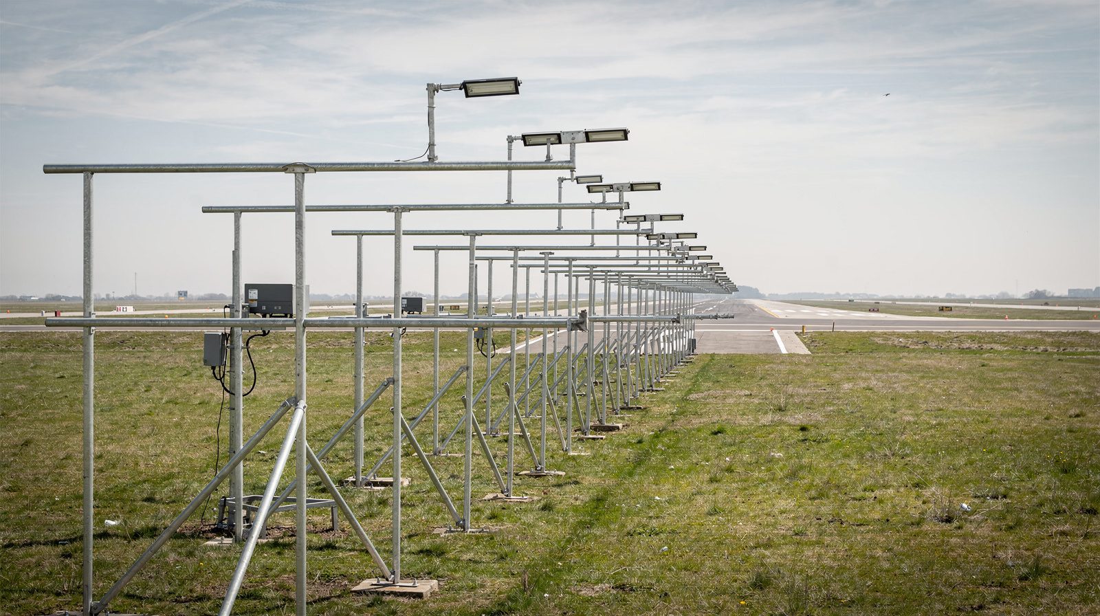
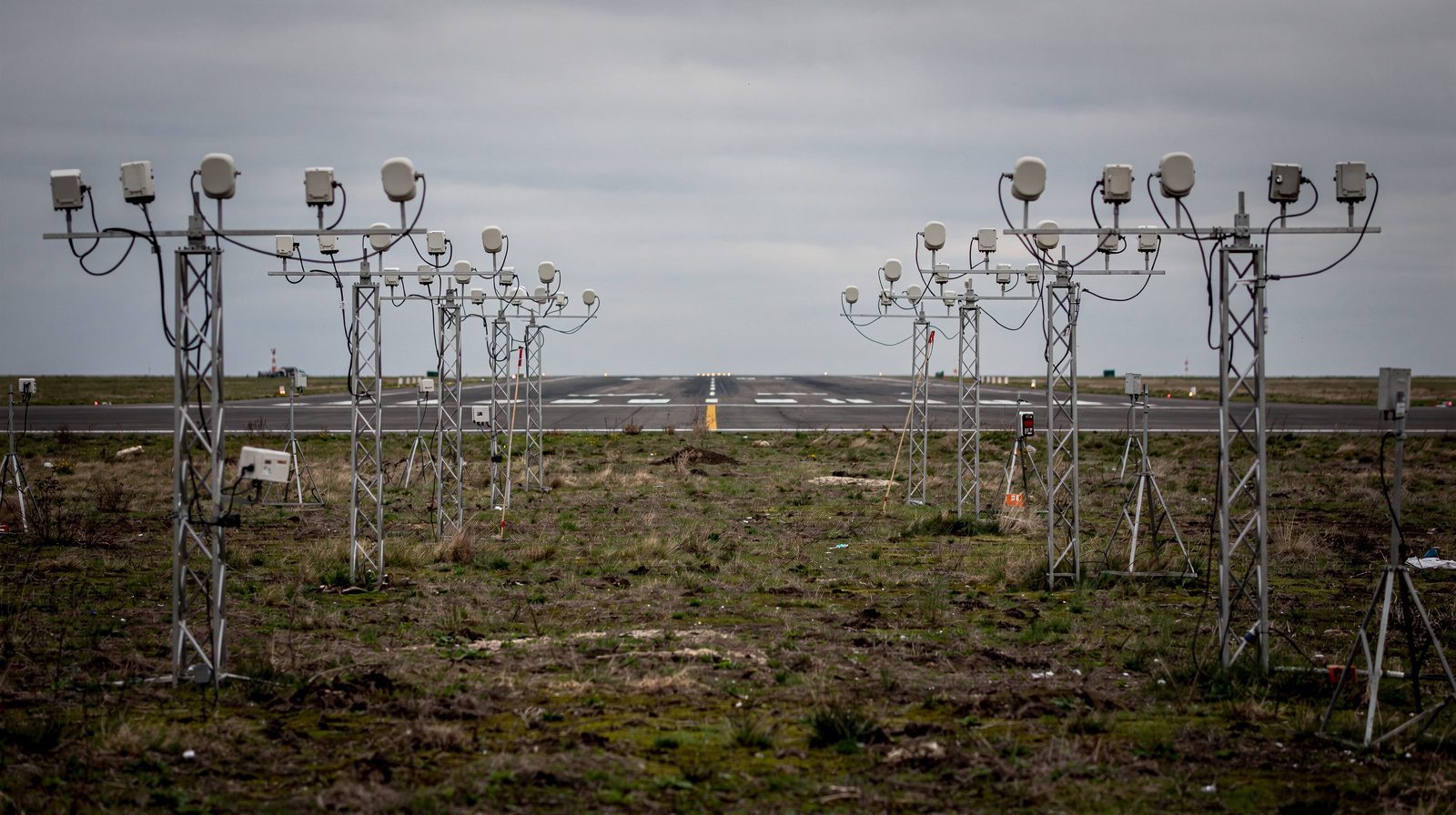
Approach Lighting System with Sequenced Flashing Lights (ALSF) is a high-intensity, precision approach lighting system installed at the approach end of instrument runways. Its primary function is to provide clear, standardized visual cues for pilots transitioning from instrument flight to visual landing, particularly in low or marginal visibility. ALSF systems combine fixed (steady-burning) and dynamic (sequenced flashing) lights, arranged along the runway centerline and crossbars, extending 2,400 feet (732 meters) from the runway threshold in the standard FAA installation.
Where Used:
In the FAA’s current order (JO 6850.2C) the ALSF-2 serves runways with Category II (CAT II) and Category III (CAT III) precision approaches. Category I runways are served by the medium-intensity SSALR, MALS, MALSF and MALSR systems.
How Used:
Pilots rely on ALSF for orientation, alignment, and descent guidance during final approach, especially under instrument meteorological conditions (IMC) such as fog, rain, snow, or at night. The system helps pilots identify the runway environment, align with the centerline, and safely descend for landing.
References:
- ICAO Annex 14, Volume I – Aerodrome Design and Operations
- FAA Airport Lighting Aids
- Wikipedia: Approach Lighting System
ALSF System Purpose and Function
Primary Purposes:
- Positive Runway Identification: Enables pilots to quickly and accurately locate the runway environment in low visibility.
- Transition Guidance: Facilitates the shift from instrument flight to visual cues during approach and landing.
- Alignment and Orientation: Assists with lateral alignment, vertical guidance, and roll orientation.
- Workload Reduction: Offers highly visible, intuitive light patterns that reduce pilot workload and improve situational awareness.
- Operational Continuity: Supports safe runway operations, maximizing airport capacity even in adverse weather.
Real-World Example:
On a foggy morning, the ALSF-2’s sequenced flashing lights are often the first visual cues a pilot sees after descending below minimums, providing crucial alignment and descent path information to complete a safe landing.
ALSF Technical Specifications
System Components
Steady-Burning White Lights:
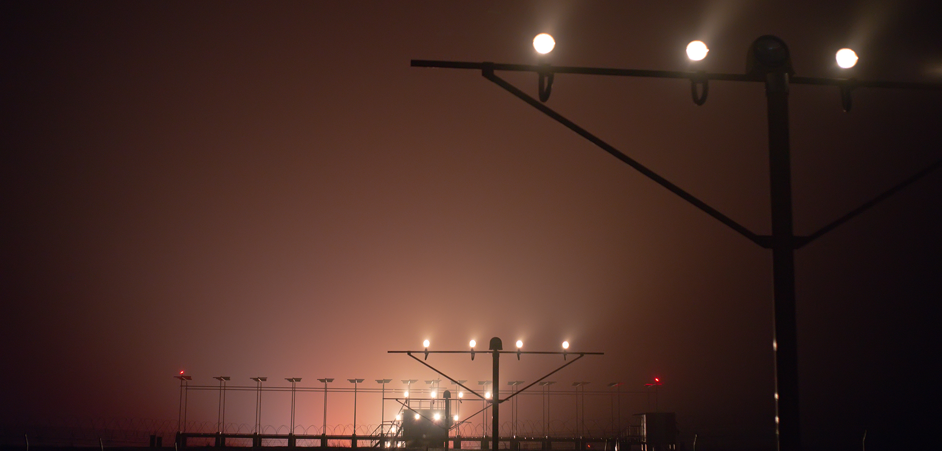
Placed along the extended centerline and crossbars at regular intervals (usually every 100 ft/30 m). Serve as persistent references for alignment and descent.Sequenced Flashing Lights (SFL, “Rabbit”):
High-intensity strobes arranged along the centerline, flashing in sequence toward the runway threshold to create a moving light effect, enhancing depth perception and guiding pilots toward the runway.Threshold Lights:
Green steady-burning lights marking the beginning of the usable runway for landing.Side Row-Bar Red Lights (ALSF-2 only):
Bars of three steady-burning red lights either side of the centreline at each light station in the inner 900 ft, highlighting the lateral boundaries and helping with roll orientation.1,000-foot Bar:
A crossbar of 21 lights, 100 ft wide, 1,000 feet (305 m) from the runway threshold. The FAA calls it the 1,000-foot distance marker crossbar. It gives a distance and roll reference. A shorter crossbar sits at 500 ft.
Typical ALSF-2 Configuration
| Component | Arrangement/Quantity |
|---|---|
| Steady-burning white lights | Centerline & crossbars, up to 144 units |
| Green threshold lights | 49 units at the runway threshold |
| Red side row-bar lights | 54 units (9 stations × 3 lights × 2 sides) |
| Sequenced flashing lights (SFL) | 15 units along centerline |
Length:
- ALSF-2: 2,400 ft (732 m)
- Centreline bars every 100 ft (30 m) from 100 ft out, with crossbars at 500 ft and 1,000 ft.
References:
Sequenced Flashing Lights (SFL) – Role and Operation
Definition
Sequenced Flashing Lights (SFL) are a critical component of ALSF, consisting of high-intensity strobes that illuminate in rapid sequence along the approach centerline, creating the “rabbit” effect.
Purpose and Effect:
- Highly visible in poor weather, low light, and at night.
- The moving flash sequence draws the pilot’s attention and provides dynamic depth, alignment, and directional cues.
- The sequence terminates at the decision bar (1,000 ft from threshold) to avoid distraction during the final landing phase.
Technical Details:
- Sequence Rate: 2 cycles per second (ICAO/FAA standard)
- Synchronization: Essential for a uniform, unmistakable effect, any malfunction can compromise safety.
- Adjustable Intensity: Light output is adjustable to match ambient conditions, controlled by ATC or pilot.
References:
- ICAO Annex 14, Volume I
- FAA Airport Lighting Aids
ALSF System Configurations
ALSF-2
- Use: CAT II/III precision approach runways (Order JO 6850.2C)
- Features:
- 2,400 ft (732 m) long, centreline bars of five white lights every 100 ft
- Crossbars at 500 ft and 1,000 ft
- Red side row bars over the inner 900 ft
- 15 sequenced flashers on the outer centreline bars
- Five intensity steps
- Can run in SSALR mode, a medium-intensity subset, in favourable weather
ALSF-1
- Status: an older configuration. It appears next to the ALSF-2 in the approach lighting drawings of the FAA AIM (Figure 2-1-1), with white centreline bars, a 1,000 ft crossbar, sequenced flashers and red bars near the threshold, but no side row bars.
- The current FAA order (JO 6850.2C) and AC 150/5340-30J do not describe the ALSF-1 and give no dimensions for it.
References:
- FAA AIM 2-1-1: Approach Light Systems
- FAA Order JO 6850.2C, Visual Guidance Lighting Systems
ALSF Operation and Use
- ATC Control: ALSF intensity and operation are adjusted by air traffic controllers according to weather and traffic needs.
- Visual Cues:
- 1,000-foot Bar: A distance and roll reference in the last part of the approach.
- Color Coding: Green (threshold), white (alignment), red (side row-bars).
Operational Scenarios:
- Low-Visibility Approaches: ALSF-2 provides essential cues for safe landings in fog, snow, or heavy rain.
- Night Operations: ALSF outlines the approach and runway area, aiding spatial orientation.
ALSF Regulatory Standards
- ICAO (Annex 14) and EU (CS-ADR-DSN):
- Specify approach lighting by function, in metres: simple, precision CAT I and precision CAT II and III
- Do not use the FAA system names
- FAA (Order JO 6850.2C):
- ALSF-2, high intensity, for CAT II and III
- SSALR, MALS, MALSF and MALSR, medium intensity, for CAT I
| Standard | CAT I Runway | CAT II/III Runway |
|---|---|---|
| ICAO / EU | Precision CAT I system, 900 m | CAT II/III system with red side rows, 900 m |
| FAA | SSALR or MALSR, 2,400 ft | ALSF-2, 2,400 ft |
| Flashers (FAA) | 5 RAIL flashers | 15 sequenced flashers |
References:
- ICAO Annex 14, Volume I
- FAA AIM: Airport Lighting Aids
ALSF Historical Context
- Origins: Post-WWII, first used at Arcata–Eureka Airport, California, to aid approaches in fog.
- Technology Evolution:
- 1950s: Introduction of high-intensity strobe (SFL) at JFK, New York.
- Global standardization by ICAO and FAA followed.
- Modernization:
- LED technology, digital controls, remote monitoring, and automatic fault detection are now common.
Image Gallery:
Approach Lighting Systems on Wikimedia Commons
Related Lighting Systems
- MALSR: Medium Intensity Approach Lighting System with Runway Alignment Indicator Lights, used for CAT I runways.
- SSALR: Simplified Short Approach Lighting System with RAIL, a medium-intensity operating mode of an ALSF-2/SSALR installation, used in favourable weather.
- REIL: Runway End Identifier Lights, synchronized flashing lights at threshold ends.
- PAPI/VASI: Visual glide path aids (red/white lights) indicating correct approach angle.
- HIRL: High Intensity Runway Lights, outline the runway edges.
References:
ALSF Examples and Use Cases
Example 1: CAT III ILS Approach in Fog
An Airbus A350 approaches a major international airport in dense fog. The ALSF-2’s sequenced flashing lights (“rabbit”) are the first visual cues below minimums, guiding the pilot with dynamic and static references to complete a safe landing.
Example 2: Nighttime Operations at a Hub
A Boeing 737 on CAT II approach at night uses the ALSF-2’s white centerline and crossbar lights, red side row-bars, and sequenced flashing lights to transition smoothly from instrument to visual references.
Summary
ALSF systems are critical components of global airport infrastructure, providing the visual guidance necessary for safe, efficient landings under instrument approach procedures. Their standardized configuration and operation, set by the FAA and matched by function in ICAO Annex 14 and CS-ADR-DSN, help ensure safety and capacity at airports worldwide, regardless of weather or visibility.
Further Reading:
- ICAO Annex 14, Aerodrome Design and Operations
- FAA Airport Lighting Aids
- Wikipedia: Approach Lighting System
Frequently Asked Questions
- What does ALSF stand for in airport lighting?
- ALSF stands for Approach Lighting System with Sequenced Flashing Lights, a high-intensity airport lighting configuration used at the approach end of instrument runways. It provides both steady and sequenced lights to guide pilots during landing, especially in low visibility conditions.
- What is the difference between ALSF-1 and ALSF-2?
- ALSF-2 is the system the FAA installs and specifies today, in Order JO 6850.2C: 2,400 ft long, for CAT II and III runways, with red side row bars over the inner 900 ft. ALSF-1 is an older configuration that appears in the FAA AIM drawings with red bars near the threshold and no side row bars. The current FAA order and advisory circular give no dimensions for it.
- How do sequenced flashing lights (SFL) work in ALSF systems?
- Sequenced flashing lights, known as the 'rabbit,' are high-intensity strobes aligned along the approach centerline. They flash in rapid sequence toward the runway threshold, creating a moving light effect that draws the pilot’s attention and improves depth perception, alignment, and situational awareness during approach.
- Why are ALSF systems important for airport operations?
- ALSF systems are crucial for maintaining safe and efficient airport operations in low visibility, such as fog, heavy rain, or night conditions. They maximize runway utilization and safety by providing pilots with unambiguous visual references needed to land safely under instrument approach procedures.
- Who sets the standards for ALSF systems?
- ALSF is an FAA name. The FAA specifies the ALSF-2 in Order JO 6850.2C and AC 150/5340-30J. ICAO Annex 14 and the EU CS-ADR-DSN do not use the name: they specify approach lighting by function, as simple, precision CAT I and precision CAT II and III systems, in metres. An ALSF-2 is the FAA system closest to the ICAO CAT II and III pattern.
This is a reference entry. TarmacView provides drone inspection services and doesn't sell the equipment or materials described in this glossary.