What is an Approach Lighting System (ALS)?
Approach Lighting System (ALS)
Definition
An Approach Lighting System (ALS) is a standardized, high- or medium-intensity lighting array installed symmetrically along the extended centerline of a runway, beginning at the threshold and extending outward into the approach zone. ALS serves as a critical visual aid, guiding pilots during the final phases of approach and landing, especially under reduced visibility conditions such as fog, rain, snow, or at night.
ALS configurations are engineered according to stringent international (ICAO Annex 14) and national (FAA AC 150/5340-30J) regulations, ensuring consistent performance and safety at airports globally. ALS is essential for runways supporting Instrument Approach Procedures (IAPs), especially those with Instrument Landing Systems (ILS) for precision approaches.
Where is ALS used?
- Commercial airports (precision/non-precision approaches)
- Military and cargo airfields (all-weather operations)
- Regional and general aviation airports
- Heliports and special-use landing areas (modified ALS)
Key Functions:
- Provides runway alignment, height, and roll cues
- Enables safe transition from IFR (Instrument Flight Rules) to VFR (Visual Flight Rules)
- Reduces approach minima, increasing operational capacity
References:
Purpose and Function
ALS is designed to provide unambiguous, high-visibility guidance during approach and landing. Its primary function is to support the safe transition from instrument-based navigation to visual landing cues.
Key Purposes
- Runway Alignment: Centerline lights and crossbars help maintain alignment with the approach path.
- Distance and Height Perception: Spacing of lights provides depth cues for judging distance and descent rate.
- Roll and Horizon Reference: Crossbars and side rows offer critical orientation cues.
- Low Visibility Transition: ALS enables pilots to visually acquire the runway at or before the Decision Altitude/Height (DA/DH).
- Reduced Minima: ALS enables lower visibility minima, increasing airport usability.
- Visual Illusion Mitigation: ALS counters black hole and featureless terrain illusions.
Operational Impact:
- With ALS: Lower RVR (Runway Visual Range) limits, more arrivals in poor visibility.
- Without ALS: Higher minima, reduced operational reliability.
Key References:
Technical Description
System Layout
ALS layouts are meticulously engineered for continuous visual guidance from the approach zone to the runway threshold. Components typically include:
- Centerline Lightbars: Linear arrays spaced at 30 m (ICAO) or 100 ft (FAA), extending up to 900 m or more.
- Crossbars: Transverse lights at set intervals (e.g., 300 m, 600 m) for horizon cues.
- Side Row Bars: Parallel rows (often red) for width and roll reference (CAT II/III).
- Sequenced Flashing Lights (SFL/“Rabbit”): High-intensity strobes flashing towards the threshold, aiding depth perception.
- Decision Bar: Crossbar at 305 m (1,000 ft) from threshold for visibility assessment.
- Threshold Lights: Green lights marking the runway’s usable start.
Light Types and Intensity
- High-Intensity ALS (HIALS): Precision approaches, intensity adjustable.
- Medium-Intensity ALS (MIALS): Regional/non-precision.
- Low-Intensity ALS: Small airports/heliports.
Light Sources
- Halogen/Xenon: Traditional, reliable sources.
- LED: Modern, energy-efficient, low-maintenance.
System Control
- ATC-Controlled: Air traffic control adjusts intensity.
- Pilot-Controlled (PCL): Pilots adjust at some non-towered airports.
Example: ALSF-2 Layout
- Length: 2,400 ft (732 m)
- Lights: 247 steady, 15 sequenced flashers
- Config: Centerline, crossbars, red side rows, SFLs
- Application: ICAO/FAA CAT II/III runways
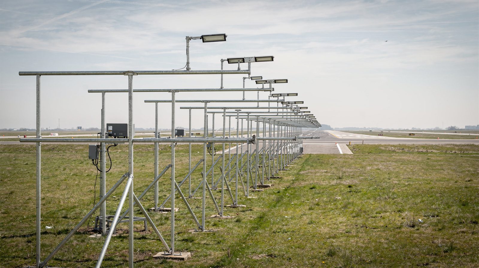
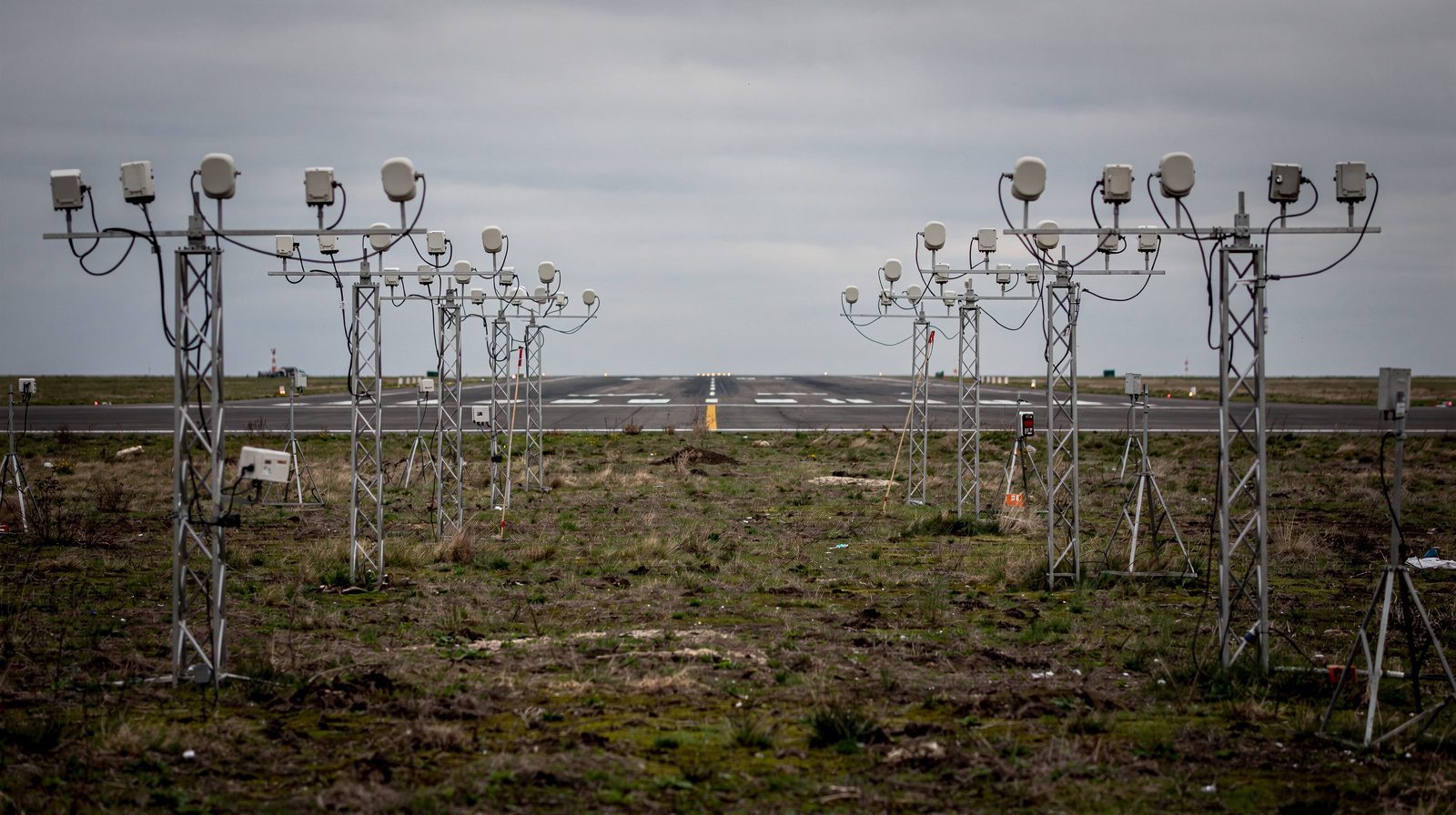
Reference Images:
Configurations and Types
ALS Types Overview
| Acronym | Description | Typical Use | System Length | Features |
|---|---|---|---|---|
| ALSF-1 | High-intensity with sequenced flashers, centerline/crossbars | CAT I Precision | 2,400 ft | SFL, crossbars |
| ALSF-2 | Adds red side rows, decision bar | CAT II/III Precision | 2,400 ft | Side rows, SFL |
| MALSR | Medium-intensity, with RAILs | CAT I Precision | 2,400 ft | RAILs, crossbar |
| MALS | Medium-intensity, basic setup | Non-precision/visual | 1,400 ft | Centerline/crossbar |
| MALSF | Medium-intensity, with sequenced flashers | Non-precision/visual | 1,400 ft | SFL, crossbar |
| SSALR | Simplified, short ALS with RAIL | CAT I Precision | 2,400 ft | RAIL, crossbar, centerline |
| SSALS | Simplified, short ALS | Small/limited sites | Variable | Centerline, crossbar |
| ODALS | Omnidirectional flashing system | Non-precision/secondary | Variable | Flashers visible from all approach angles |
| SALS | Short ALS, minimum ICAO config | Small airports | 420 m (min) | Centerline, 1 crossbar |
| LDIN | Lead-in lighting for curved/offset approaches | Offset/complex approaches | Variable | Guides offset approach path |
Key Features
- ALSF-1/2: Full-length, high-intensity, SFL, crossbars, and (in ALSF-2) red side rows/decision bar.
- MALSR/MALS/MALSF: Medium intensity, suitable for regional airports, may include RAIL or SFL. MALS and MALSF are 1,400 ft non-precision systems. MALSR extends the same 1,400 ft steady barrettes with a 1,000 ft runway alignment indicator light (RAIL) sequence, giving a full 2,400 ft precision CAT I system.
- SSALR/SSALS/ODALS: SSALS is a simplified short system, and ODALS is an omnidirectional flashing aid for non-precision approaches. SSALR adds a RAIL to SSALS for a full-length 2,400 ft CAT I configuration.
- SALS/LDIN: Minimal or specialized for unique approach paths.
References:
Key Components
Centerline Lights
- Purpose: Defines runway alignment.
- Configuration: Steady white, spaced per ICAO/FAA.
- Length: Varies by ALS type.
Crossbars
- Purpose: Horizon/roll reference.
- Configuration: White, at set intervals.
Side Row Bars
- Purpose: Width/roll cues.
- Configuration: Red or white, parallel to centerline (CAT II/III).
Sequenced Flashing Lights (SFL/“Rabbit”)
- Purpose: Dynamic depth/alignment cues.
- Operation: 2 Hz sequential flashes.
Runway Alignment Indicator Lights (RAIL)
- Purpose: Flashing alignment cues.
- Usage: MALSR/SSALR.
Decision Bar
- Location: 305 m (1,000 ft) from threshold.
- Purpose: DA/DH visual assessment.
Threshold Lights
- Purpose: Start of runway.
- Configuration: Steady green across threshold.
References:
Operational Context and Use Cases
Transition from Instrument to Visual
- Critical Phase: Occurs at or before DA/DH, ALS ensures sufficient cues to continue descent/landing safely.
Integration with Instrument Approach Procedures
- Precision Approaches (ILS CAT I/II/III): ALS mandatory for lower minima, ALSF-2 used for CAT II/III.
- Non-Precision Approaches: MALS/MALSR/ODALS provide essential guidance.
Visibility Minima Reduction
- With ALS: Minima as low as 200 m RVR for CAT III.
- Without ALS: Higher minima, reduced reliability.
Use Cases
- Major Airport: ALSF-2 supports frequent CAT III operations.
- Regional Airport: MALSR keeps airport open in marginal weather.
- General Aviation: ODALS/SALS enhance safety.
References:
Historical Development
Early Systems
- Origins: Simple floodlights/incandescent lamps in the 1920s–30s.
- Night Flying: ALS development driven by military and commercial needs.
Post-WWII Advances
- Arcata–Eureka Airport: First full-scale ALS for foggy conditions.
- US Navy/United Airlines: Developed high-mounted, strobe-based ALS.
Standardization and Modernization
- Centerline/Crossbar Configuration: “U.S. Standard” adopted globally.
- Calvert System (UK): Introduced horizon bars, influenced ICAO.
- Sequenced Flashing Lights: Added in the 1960s for dynamic guidance.
Modern Developments
- ICAO/FAA Collaboration: Ongoing refinement of layout, color, intensity.
- LED Technology: Energy savings, lower maintenance.
- Smart Monitoring: Integration with airport lighting control systems.
References:
Regulatory Standards and Compliance
ICAO Standards
- Annex 14, Volume 1: Defines ALS requirements for system length, spacing, color, intensity, and maintenance.
- Categories: Simple, CAT I, and CAT II/III precision ALS.
- Maintenance: Mandates regular inspection, testing, and cleaning.
FAA Standards
- AC 150/5340-30J: U.S. ALS types, layout, intensity, and control.
- Operational Control: Manual/automatic intensity adjustment.
- Maintenance: Routine inspection/testing required.
Impact on Procedures
- 14 CFR §91.175: Approach minima conditional on ALS, outages require higher minima or alternate procedures.
References:
Impact on Flight Operations and Aviation Safety
Enhanced Safety
- Illusion Mitigation: Counters black hole and featureless terrain illusions.
- CFIT Prevention: Reduces risk of Controlled Flight Into Terrain.
- Standardization: Consistent layouts aid pilot situational awareness.
Operational Capacity
- Lower Minima: More arrivals/departures in poor visibility.
- Reduced Delays: Improved all-weather reliability.
Human Factors
- Cognitive Load: Structured cues reduce pilot workload and fatigue.
Notable Safety Outcomes
- Accident Reduction: Fewer approach and landing accidents at ALS-equipped airports.
References:
Summary
Approach Lighting Systems (ALS) are a cornerstone of modern aviation safety, providing essential visual cues that enable pilots to safely transition from instrument flight to landing, even under challenging visibility conditions. ALS design, configuration, and maintenance are governed by strict international and national standards, supporting low-minima operations and enhancing safety and operational capacity at airports worldwide.
For further details, consult:
Frequently Asked Questions
- What is the main purpose of an Approach Lighting System (ALS)?
- ALS provides the critical visual cues that guide pilots from instrument-based flight to a safe visual landing, especially in conditions of reduced visibility. It enables precise runway alignment, depth perception, and minimizes the risk of approach and landing accidents.
- How does ALS affect landing minima at airports?
- A compliant ALS allows for lower visibility minima on instrument approaches, enabling landings in poorer weather conditions. Without ALS, higher minima are required, reducing airport capacity and reliability in low-visibility conditions.
- What are the main types of ALS?
- Key ALS types include ALSF-1, ALSF-2 (for precision approaches), MALSR, MALS, MALSF (for non-precision and regional airports), SSALR, SSALS, ODALS, and SALS, each with specific layouts and intensity suited to different operational requirements.
- What regulations govern ALS design and installation?
- ALS design and installation are governed internationally by ICAO Annex 14 and nationally (in the U.S.) by FAA AC 150/5340-30J. These standards specify system length, light intensity, color, spacing, and maintenance protocols.
- Why are sequenced flashing lights (SFL) important in ALS?
- Sequenced flashing lights, often called 'the rabbit', create a dynamic visual effect that enhances depth perception and guides pilots' eyes to the runway threshold, especially useful in low-visibility or night operations.
This is a reference entry. TarmacView provides drone inspection services and doesn't sell the equipment or materials described in this glossary.