What is Lead-In Lighting?
Lead-In Lighting – Lights Extending Approach Lighting Toward Runway
Definition: What Is Lead-In Lighting?
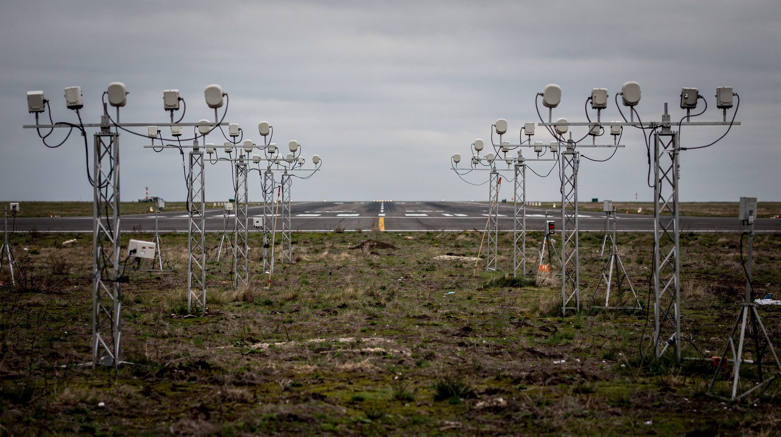
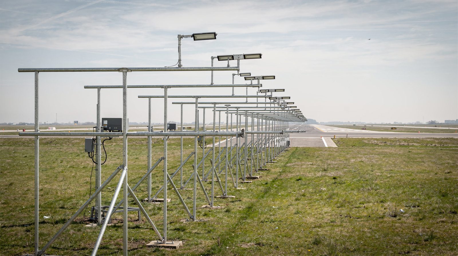
Lead-in lighting (formally, Lead-In Lighting System or LDIN) is a specialized airport lighting system comprised of highly visible lights installed in a pattern, often curved or offset, to mark a designated approach path to a runway. Unlike standard approach lighting, which extends straight outward from the runway centerline, lead-in lighting is used where the final approach course is not aligned with the runway due to obstacles, terrain, airspace constraints, or environmental considerations. It provides unmistakable visual cues for pilots transitioning from instrument to visual flight, especially during complex approaches.
Key Characteristics:
- Series of steady or flashing white lights, arranged in linear, curved, or segmented patterns
- Indicates a protected, obstacle-free approach corridor
- Used as a “visual bridge” from the end of an instrument approach to the main approach lighting or runway threshold
- Defined and regulated by ICAO Annex 14 and FAA standards
Purpose and Operational Role
The primary role of lead-in lighting is to ensure pilots can safely and unmistakably follow a designated approach path when a straight-in approach isn’t possible. This is common at airports surrounded by terrain, urban areas, or airspace requiring curved or offset approach segments.
Benefits and Functions:
- Provides continuous, positive visual guidance for non-standard approaches
- Enhances safety by reducing ambiguity, risk of misalignment, and controlled flight into terrain (CFIT)
- Supports safe transitions from instrument navigation to visual flight, especially in poor weather or at night
- Aids in noise abatement by routing aircraft away from sensitive areas
Lead-In Lighting Roles
| Operational Role | Description |
|---|---|
| Visual Guidance | Directs pilots along safe, defined approach paths |
| Transition Aid | Bridges instrument and visual flight segments |
| Obstacle Avoidance | Guides aircraft around terrain or urban obstacles |
| Noise Abatement Support | Enables routing away from sensitive areas |
| CFIT Risk Reduction | Minimizes misalignment and terrain collisions |
How Lead-In Lighting Is Used
Pilot workflow with LDIN:
Approach Initiation:
When flying a procedure that ends with a curved or offset visual segment, pilots are briefed via charts and NOTAMs about the presence and pattern of lead-in lighting.Visual Acquisition:
As the aircraft nears minimums, pilots scan for the lead-in lights, which are visible from several miles out. Their unique color and pattern distinguish them from other lights.Following the Lights:
Upon sighting, pilots visually track the illuminated path. Curves or turns are marked by flashing or intensified lights.Transition to Standard ALS:
At the end of the LDIN, pilots intercept the main approach lighting system or runway, using standard runway cues for final alignment and landing.
Example: JFK’s Canarsie Approach (13L/13R):
Aircraft avoid noise-sensitive neighborhoods by following a curved path marked by lead-in lights over Jamaica Bay and the Canarsie area. The system ensures precise navigation, even in low visibility.
Typical Configurations and Layout
Standard LDIN Setup
- Linear or Curved:
The light pattern matches the required approach path, straight, gently curved, or sharply segmented. - Lights:
High-intensity steady white lights, with clusters or flashers at turns. - Spacing:
Straight segments: 200–300 ft (60–90 m) apart, Curves/turns: 100–200 ft (30–60 m). - Extent:
Usually extends 1,000–3,000 ft (300–900 m), or longer, from the entry point to main ALS or runway threshold. - Mounting:
Flush with surface, on low mounts, or on piers/bridges if over water.
| Segment | Typical Spacing (ft/m) | Light Type |
|---|---|---|
| Straight | 200–300 (60–90) | Steady White |
| Curve/Turn | 100–200 (30–60) | Flashing/Cluster |
ALS vs. Lead-In Lighting:
| Feature | ALS (Standard) | Lead-In Lighting (LDIN) |
|---|---|---|
| Alignment | Straight, centerline | Curved/offset, as needed |
| Purpose | Straight-in finals | Curved/offset guidance |
| Location | Ahead of threshold | From end of instrument segment |
| Light Types | Steady/flashers (SFL) | Steady, flashing, clusters |
| Usage | Precision/straight-in | Offset/curved approaches |
Color Codes, Spacing, and Visual Cues
- Color:
Always white, for high conspicuity and to avoid confusion with other airfield lighting (runway green/edge white, taxiway blue, runway-end red). - Special Segments:
Flashing white lights or clusters at turns or intersections to highlight course changes. - Spacing:
200–300 ft (60–90 m) for straight, 100–200 ft (30–60 m) at curves.
What Pilots See:
A highly visible “string of pearls” or arc of white lights, with bright clusters or flashers marking turns. At night or in poor visibility, the pattern stands out, providing unambiguous guidance.
Regulatory Standards and References
- ICAO Annex 14, Vol I:
Defines LDIN lighting standards, layout, color, and visibility requirements. - FAA AIM, AC 150/5340-30:
Details U.S. design and operational standards for lead-in lighting. - Charting:
All approach charts, airport diagrams, and AIPs for affected airports show lead-in lighting systems.
Installation:
Only implemented where justified by operational need, obstacles, noise abatement, non-straight approaches.
Examples and Use Cases
| Airport | Runway/Approach | Description |
|---|---|---|
| JFK International (NY, US) | 13L/13R “Canarsie” | Curved, light-guided city-avoidance approach |
| Kai Tak (Hong Kong, closed) | 13 “Checkerboard” | Sharp turn, lead-in lights mark the path |
| Innsbruck (Austria) | 08, 26 | Valley approaches, lead-in lights for terrain |
Operational Considerations for Pilots
- Instrument Approaches:
At some airports, the missed approach point or minimum descent altitude (MDA) is before alignment with the runway. Pilots must acquire and follow the lead-in lights for safe final approach. - Night/Low-Visibility:
LDIN is invaluable at night or in IMC, reducing workload and the risk of spatial disorientation. - Briefing:
Always brief LDIN use via approach charts and NOTAMs.
Summary
Lead-in lighting (LDIN) is a critical airport lighting system that safely guides pilots along curved or offset approach paths, bridging the gap between complex instrument procedures and the final runway alignment. By providing clear, unmistakable visual cues, LDIN ensures safe landings in even the most challenging operational environments.
If your airport or operation requires enhanced approach guidance due to terrain, obstacles, or airspace complexity, consider upgrading or installing lead-in lighting to maximize safety and compliance.
Frequently Asked Questions
- When is lead-in lighting required at an airport?
- Lead-in lighting is required when the published approach procedure to a runway is not coincident with the extended runway centerline, often due to obstacles, terrain, airspace restrictions, or noise abatement procedures. It provides positive visual guidance along curved, offset, or segmented approach paths.
- How does lead-in lighting differ from standard approach lighting systems (ALS)?
- Standard ALS is aligned with the runway centerline and supports straight-in precision approaches. Lead-in lighting is supplementary, marking offset or curved approach segments to guide aircraft from the end of an instrument approach to the main ALS or runway threshold.
- What color and pattern are lead-in lights?
- Lead-in lights are always white for maximum conspicuity. They may be steady-burning or flashing, with clusters or intensified lights at curves or turning points. The layout can be straight, curved, or segmented based on the required approach path.
- Are lead-in lighting systems depicted on approach charts?
- Yes, all published approach charts, airport diagrams, and Aeronautical Information Publications (AIP) for airports with lead-in lighting systems clearly depict their presence and configuration. Pilots are briefed to use them as part of approach planning.
- Can lead-in lighting be used for noise abatement?
- Absolutely. Lead-in lighting often supports noise abatement procedures by guiding aircraft along precise paths that avoid noise-sensitive areas, urban centers, or protected environments during visual approach segments.
This is a reference entry. TarmacView provides drone inspection services and doesn't sell the equipment or materials described in this glossary.