What is a deflection angle?
Deflection Angle – Technical Glossary & Application Guide
Definition and Core Concept
Deflection angle in photometry is the angle between the main axis of a light beam emitted from a luminaire and the reference mounting orientation or axis of the fixture. It is a fundamental parameter in lighting design, describing not just the geometric direction in which the strongest light is projected, but also forming a basis for compliance with safety and operational standards in fields such as aviation lighting.
In practical terms, a ceiling-mounted fixture with a deflection angle of 0° emits light directly downward (perpendicular to the mounting surface). If the beam is intentionally directed 30° away from the perpendicular, the deflection angle is 30°. This measurement becomes essential when luminaires must be aimed to avoid glare, highlight specific features, or meet regulatory requirements, especially in critical environments like airfields, where precision can directly impact safety.
Deflection Angle vs. Beam Angle vs. Field Angle
While often used together, these three terms refer to different aspects of a luminaire’s output:
| Term | Definition | Use Case Example | Standard Unit |
|---|---|---|---|
| Deflection Angle | Angle between beam axis and fixture mounting orientation | Directs runway threshold lights for pilot approach | Degrees (°) |
| Beam Angle | Angle where intensity drops to 50% of maximum | Specifies spread of apron floodlight | Degrees (°) |
| Field Angle | Angle where intensity drops to 10% of maximum | Defines visible extent of taxiway edge lights | Degrees (°) |
- Deflection Angle: Determines the beam’s “aim” or direction.
- Beam Angle: Describes the width of the high-intensity core of the beam.
- Field Angle: Marks the limits of significant illumination.
Correct specification of all three is essential for effective and safe lighting, whether spotlighting artwork or guiding aircraft to safe landings.
Photometric Measurement Techniques
Goniometric Measurements
A goniometer or goniophotometer is the primary instrument for measuring the deflection angle and photometric properties of a luminaire. The fixture is rotated about one or more axes, and light intensity is recorded at various angular positions. The result is a matrix of luminous intensities, allowing engineers to pinpoint the direction of maximum intensity (the deflection angle) and determine beam and field angles.
In aviation, international standards (e.g., ICAO Annex 14, FAA AC 150/5345-46) mandate goniometric testing for all airfield lighting to ensure the output is correctly aligned and distributed.
Polar Photometric Diagrams
Polar diagrams visually represent how intensity varies with angle around the luminaire. The length of each radius indicates intensity at that angle, with the peak pointing in the direction of the deflection angle.
These diagrams are vital tools for designers and inspectors, confirming that the main beam is aimed as intended.
IES and Photometric Data Files
Manufacturers provide detailed photometric data in standardized formats (e.g., IES files), which encode measurements of intensity at numerous angles. Lighting simulation tools (DIALux, AGi32, etc.) use this data for accurate modeling, verifying that deflection, beam, and field angles meet project and regulatory requirements.
Field Measurement and Adjustment
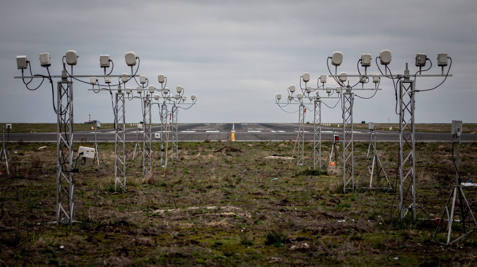
On-site aiming is often required, especially for adjustable fixtures. Installers use digital inclinometers, laser levels, or protractors to set the deflection angle, then verify with test illuminance or intensity measurements. In aviation, routine checks ensure alignment remains within tight tolerances.
Interpreting Photometric Data
How to Read Polar Diagrams
- The center represents the mounting point.
- The 0° axis is typically perpendicular to the mounting surface.
- The peak (longest radius) indicates the direction of maximum intensity, the deflection angle.
- The spread at 50% and 10% of maximum intensity defines the beam and field angles, respectively.
For example, a wall washer aimed 45° upward will show its maximum at 45°, with beam and field angles indicating the spread of the wash.
Example: Aviation and Architectural Lighting
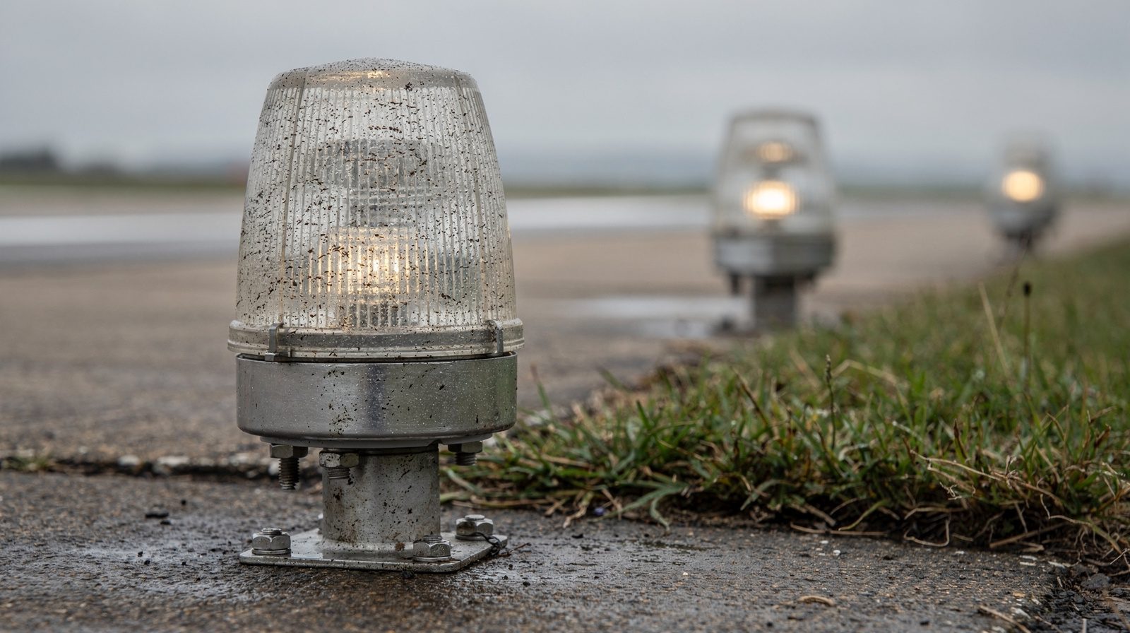
- Runway Edge Lights: Have a tightly controlled lateral deflection angle to direct light along the runway, ensuring pilots see the edge from the approach path.
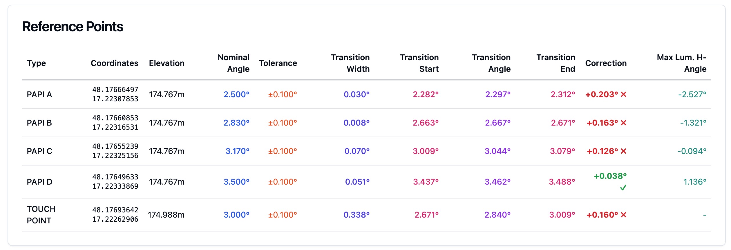
- PAPI Systems: Use arrays of luminaires, each set at specific deflection angles to create the required visual glide path.
- Museum Spotlights: Are aimed (deflection angle) to highlight art, with a narrow beam angle to focus attention.
Mnemonics
- Deflection Angle: Where you aim the flashlight.
- Beam Angle: The width of the bright core.
- Field Angle: The faintly lit periphery.
Applications and Use Cases
Aviation Lighting
Runway and Approach Lights
Correct deflection angle is critical for safety and compliance. For example, runway edge lights must emit horizontally along the runway. ICAO and FAA standards dictate precise angular tolerances. Non-compliance can compromise visibility and safety.
Precision Approach Path Indicators (PAPI)
Each lamp in a PAPI array is individually set to a precise deflection angle, creating a pattern of red and white lights that provide instant glide path feedback to pilots.
Obstruction Lighting
Tall structures require obstruction lights that are visible from all relevant approach angles, achieved through careful goniophotometric design and field alignment.
Apron and Taxiway Lighting
Wide-field but precisely aimed to avoid glare in cockpits or terminals.
Architectural and Commercial Lighting
- Wall Washers: Aimed at a fixed angle to create smooth vertical illumination.
- Spotlights: Adjustable deflection angles to highlight features or displays.
- Retail: Flexible track lights for merchandise highlighting.
Installation and Verification Checklist
- Review Manufacturer Data: Confirm default deflection angle.
- Identify Target: Establish the intended illuminated area.
- Set and Lock Fixture: Use alignment tools to aim.
- Test: Energize fixture, verify light direction and intensity.
- Document and Inspect: Record settings and check regularly for drift or misalignment.
Glossary of Related Photometric Terms
- Deflection Angle: Angular deviation from reference orientation, the beam’s “aim.”
- Beam Angle: Angle covering the high-intensity core (≥50% of max).
- Field Angle: Angle covering the faintly lit periphery (≥10% of max).
- Luminous Intensity (cd): Light output in a particular direction.
- Luminous Flux (lm): Total light output.
- Illuminance (lx, fc): Light falling on a surface.
- Luminance (cd/m²): Perceived brightness from a viewing angle.
- Polar Diagram: Circular plot showing intensity vs. angle.
- Goniometer: Instrument for measuring angular light output.
- CBCP: Center beam candle power, the maximum intensity.
- NEMA Classification: Floodlight beam width codes.
- Glare Control: Techniques to minimize distracting brightness.
- Homogeneity: Uniformity of illumination.
- Photometric Testing: Measurement and verification of lighting performance.
- Obstruction Lighting: Warning lights for tall structures.
- ALS (Approach Lighting System): Array of lights for runway approach.
- PAPI: Glide path indicator array.
- Simulation Tools: Software for lighting design with photometric data.
Aviation Lighting: Regulatory Foundations
Lighting systems at airports must comply with international standards, notably ICAO Annex 14 and FAA Advisory Circulars. These define minimum luminous intensity, color, beam spread, and, critically, the permissible deflection angle for each application. Goniometric data is required for certification and maintenance.
Routine field inspections and digital monitoring ensure ongoing compliance and operational safety.
Integration with Simulation and Emerging Technology
Modern lighting practice integrates photometric measurements with simulation software, allowing engineers to model performance and verify compliance before installation. Advances in automated goniometric systems and remote diagnostics further enhance precision and safety, especially in aviation.
Conclusion
The deflection angle is a foundational parameter in photometric science and engineering, underpinning safe and effective lighting in aviation, architecture, and beyond. Mastery of its definition, measurement, and application is essential for professionals tasked with designing, specifying, or maintaining critical lighting systems.
By specifying and verifying deflection angle with precision, using both traditional tools and modern simulation, engineers and designers can ensure lighting systems deliver exactly where needed, every time.
For deeper technical reference, consult ICAO Annex 14, FAA Advisory Circulars, IES standards, and lighting simulation software documentation.
Frequently Asked Questions
- What is the deflection angle in lighting?
- The deflection angle is the angle between the axis of the main light output from a luminaire and the reference or mounting orientation. It determines the direction in which the beam is aimed, which is crucial for applications requiring precise illumination control, such as aviation lighting and architectural spotlights.
- How is deflection angle different from beam angle and field angle?
- The deflection angle defines the direction of the beam, i.e., where the main light is aimed. Beam angle describes the spread of the beam where intensity is at least 50% of maximum, and field angle covers the wider area where intensity is at least 10% of maximum. Together, these parameters define both the direction and coverage of a luminaire.
- How is the deflection angle measured in aviation lighting?
- Deflection angle is measured using a goniometer or goniophotometer, which rotates the light fixture and records its output at precise angles. This data is analyzed to determine the exact direction of maximum luminous intensity, ensuring compliance with strict aviation safety standards.
- Why is deflection angle important in airfield lighting?
- Correct deflection angle ensures that runway, threshold, and approach lights are aimed to provide optimal visual cues to pilots, supporting safe landings and takeoffs. Misalignment can result in poor visibility, glare, or regulatory non-compliance, affecting operational safety.
- Can deflection angle be adjusted in the field?
- Yes, many directional luminaires allow for adjustment of the deflection angle during installation using inclinometers, laser levels, or manual aiming. Regular field inspections help maintain correct alignment over time, which is especially important in regulated environments like airports.
This is a reference entry. TarmacView provides drone inspection services and doesn't sell the equipment or materials described in this glossary.