How a Drone Measurement Becomes Evidence
Why a number off a drone camera can stand up as evidence: what the sensor records, how it becomes an angle, and where the uncertainty is bounded.
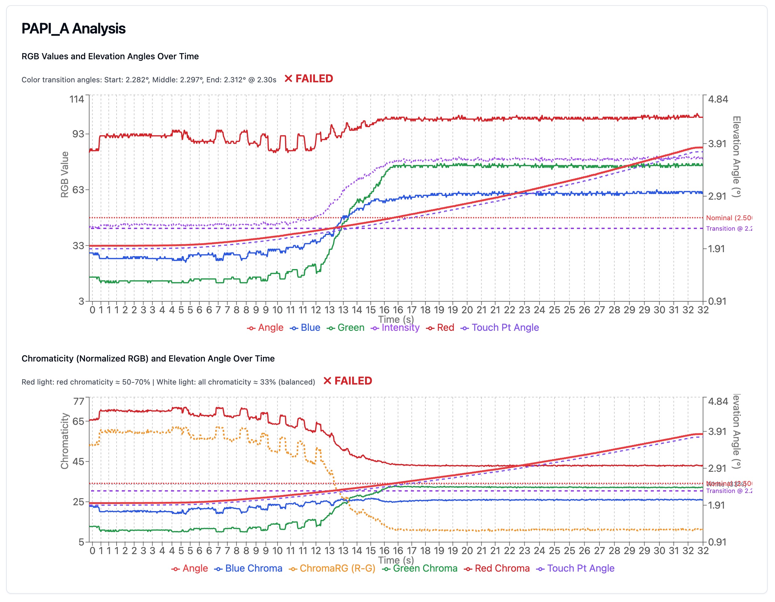 RGB VS ELEVATION · RED FRACTION · PASS
The question nobody asks out loud
An inspection report is a claim. It says a light unit sits at a particular angle, and that the angle is inside or outside tolerance. Somebody signs it, somebody files it, and a year later an auditor may ask where the number came from.
The fair version of the doubt is this. A drone carries a camera. A camera is not an instrument in the sense a photometer on a tripod is an instrument. So why should the number be believed? The answer is not that our camera is secretly a laboratory device. It is that the chain from sensor to reported value is written down, repeatable, and bounded by a stated uncertainty . That is what turns a picture into evidence, and it is worth walking the whole chain rather than asserting the conclusion.
What the sensor actually records
A camera does not record light in candelas. It records counts. Photons pass a lens, hit a sensor, get amplified by whatever gain the exposure setting selected, and are written out as integers per channel. That number depends on the lens, the aperture, the shutter, the sensor temperature, the encoding, and on how far away the light was. None of it is a physical unit.
So the honest starting point is that a raw frame is an observation, not a measurement. What makes it usable is everything attached to it. Each frame in our pipeline carries a timestamp synchronised to the drone’s RTK GNSS log, which means we know the position of the camera when the frame was taken, and we know the surveyed position of the light unit we are looking at. The frame supplies one thing only: whether the beam looked red, white, or somewhere between.
From an observation to a physical quantity
The quantity a PAPI inspection reports is an angle, and an angle is a geometry problem, not a brightness problem. Two known positions in space define an elevation angle between them. The camera’s contribution is to identify the point along that angular sweep where the signal changes.
That is what the two panels at the top of this post show. The left panel plots the raw red, green and blue channel values against elevation angle as the drone climbs through the beam. The right panel plots the red fraction, r/(r+g+b). The second is the one that carries the measurement, because a ratio of channels normalises itself. Halve the exposure and every channel halves with it, so the fraction is unchanged. Fly the same unit on a brighter day and the absolute values shift while the crossing point does not.
This matters more than it sounds. It means the reported transition angle does not depend on the camera having a known absolute response. The shaded band in the plot is the transition region, and the reported angle is fitted across it rather than read off a single frame. Hundreds of frames vote, and the noise on the trace averages down instead of landing on one lucky sample.
What calibration means here, and what it does not
There are two separate chains, and conflating them is how vendors overclaim.
The geometric chain is the strong one. Positions come from RTK GNSS referenced to a base station, which is itself tied to a geodetic reference frame. Camera intrinsics, focal length and lens distortion, come from a target-based calibration performed per lens and recorded with a date. This is ordinary instrument calibration in the metrological sense: an instrument compared against a known standard, with the comparison documented.
The optical chain is weaker and we should say so. Our airborne camera is not a calibrated photometer , and we do not issue a calibration certificate for it that would survive scrutiny as an absolute photometric reference. Where absolute intensity matters rather than a ratio, the anchor has to come from somewhere else, either a reference measurement taken on site or a cross-calibration against an instrument that does carry a certificate. Comparing units to each other on the same flight, under the same exposure, is a strong relative statement and a weak absolute one.
ISO/IEC 17025 sets out what a testing and calibration laboratory has to demonstrate about competence and results, and the Guide to the Expression of Uncertainty in Measurement sets out how to combine and report uncertainty components. Both are real frameworks with real requirements. Neither is something a company gets to claim by describing its process well. What we have is a protocol, not an accreditation, and the difference is worth being blunt about.
Where the uncertainty enters
Uncertainty is bounded, not eliminated. The budget below is the one published on our algorithm deep dive , and every figure in it is ours rather than an industry norm.
| Contributor | What it is | Our stated contribution |
|---|---|---|
| GNSS positioning | RTK vertical accuracy of ±1.5 cm, at a 350 m measurement distance | 0.0025° |
| Optical resolution | 4K sensor, 24 mm equivalent lens, one pixel ≈ 0.0133°, improved about tenfold by sub-pixel centroiding | < 0.0017° |
| Gimbal stability | Mechanical tolerance, carried into the budget even though digital stabilization corrects most of it | ±0.003° |
| Combined worst case | The three summed rather than added in quadrature, which is the conservative choice | ±0.0072° |
| What we guarantee | Deliberately looser than the computed worst case | ±0.017° (1 minute of arc) |
Two things about that table are the point. First, the guarantee is worse than the computation, on purpose, because a budget assembled in an office is not the same as a result obtained in wind at an operational airfield. Second, the whole budget sits well inside the ICAO Annex 14 colour transition tolerance of 3 minutes of arc, which is the number that decides whether a unit is out of tolerance . A measurement method only needs to be tight enough to resolve the decision it is being used to make.
Why repeatable beats precise
Given a choice between a more precise method nobody can repeat and a slightly coarser method that reproduces, take the second one.
A single very accurate reading tells you the state of a light on one afternoon. It cannot tell you whether the unit is drifting, because there is nothing to compare it against. Measurement accuracy without repeatability gives you a number and no trend. Our missions are generated from the airport profile and flown autonomously, so the same flight path is reproduced on the next visit and the two datasets are directly comparable. That is also why a verification pass after a maintenance adjustment is a comparison rather than a new survey.
Repeatability is what makes field calibration meaningful too. Verifying an instrument at its point of use, under the conditions it actually works in, is only useful if the conditions are recorded and the procedure is the same every time.
There is a second reason to prefer the stated bound. An unstated precision is not a stronger claim, it is an unfalsifiable one. If a method reports an angle and no interval around it, nobody can say whether a 2 minute difference between two visits is a real drift or noise in the method. Attaching a bound to every number is what lets a maintenance team act on a change, and it is also what allows the method to be wrong in a way somebody can demonstrate. A number that cannot be checked is not a safer number.
What holds up in an audit months later
Traceability in the regulatory sense is not only about standards. It is about being able to reconstruct how a specific number was produced, long after everyone involved has forgotten the day.
| What an auditor asks | What has to exist |
|---|---|
| Where did this number come from? | The raw video and RTK log, retained, not just the derived value |
| How was it computed? | The processing method and its version, fixed at the time of the flight |
| What was the instrument’s state? | Camera intrinsics and RTK setup, with calibration dates |
| Who did it, and under what conditions? | Operator, date, time, weather and lighting recorded with the mission |
| What was it judged against? | The tolerance cited, from the applicable standard |
✓ Retained raw data means a disputed result can be recomputed. ✗ A PDF with a number in it and nothing behind it cannot be re-examined at all.
That is the difference between a report and evidence. A report states a conclusion. Evidence lets somebody else reach the same conclusion independently.
What we claim, and what we do not
We claim a documented method, a stated uncertainty that is conservative against our own computed budget, retained raw data, and results that reproduce across visits. We do not claim laboratory accreditation, and we do not claim our airborne camera is an absolute photometric reference. Anyone who tells you their drone camera is a certified instrument has skipped a step.
If you want the specifics of what gets measured on a PAPI and the tolerance each parameter is judged against, that is on the PAPI inspection page . If you want the standard behind those tolerances, we covered it in what ICAO Annex 14 requires of your PAPI .
Founded by flight-inspection veterans who spent decades measuring PAPI lights for aviation authorities across Europe.
Learn more
Related terms
03 TERMSPhotogrammetry
Photogrammetry is the science of deriving reliable 3D measurements and geometric information from overlapping 2D photographs. In infrastructure inspection, drone-based photogrammetry creates orthomosaics, digital surface models, and 3D point clouds for measurement, change detection, and condition documentation of pavements, bridges, and buildings.
Automated Drone-Based Infrastructure Inspection
Automated drone inspection uses pre-programmed flight paths, computer vision, and AI analysis to survey infrastructure assets including runways, bridges, roads, and buildings with minimal human piloting. This technology produces consistent, repeatable data for Pavement Condition Index computation, defect detection, and change monitoring across civil aviation and transportation infrastructure.
Camera Calibration
Camera calibration determines intrinsic parameters (focal length, principal point, lens distortion coefficients) essential for accurate photogrammetric measurement. Covers calibration methods, distortion models, quality assessment, and impact on infrastructure inspection accuracy.
Further reading
03 ARTICLES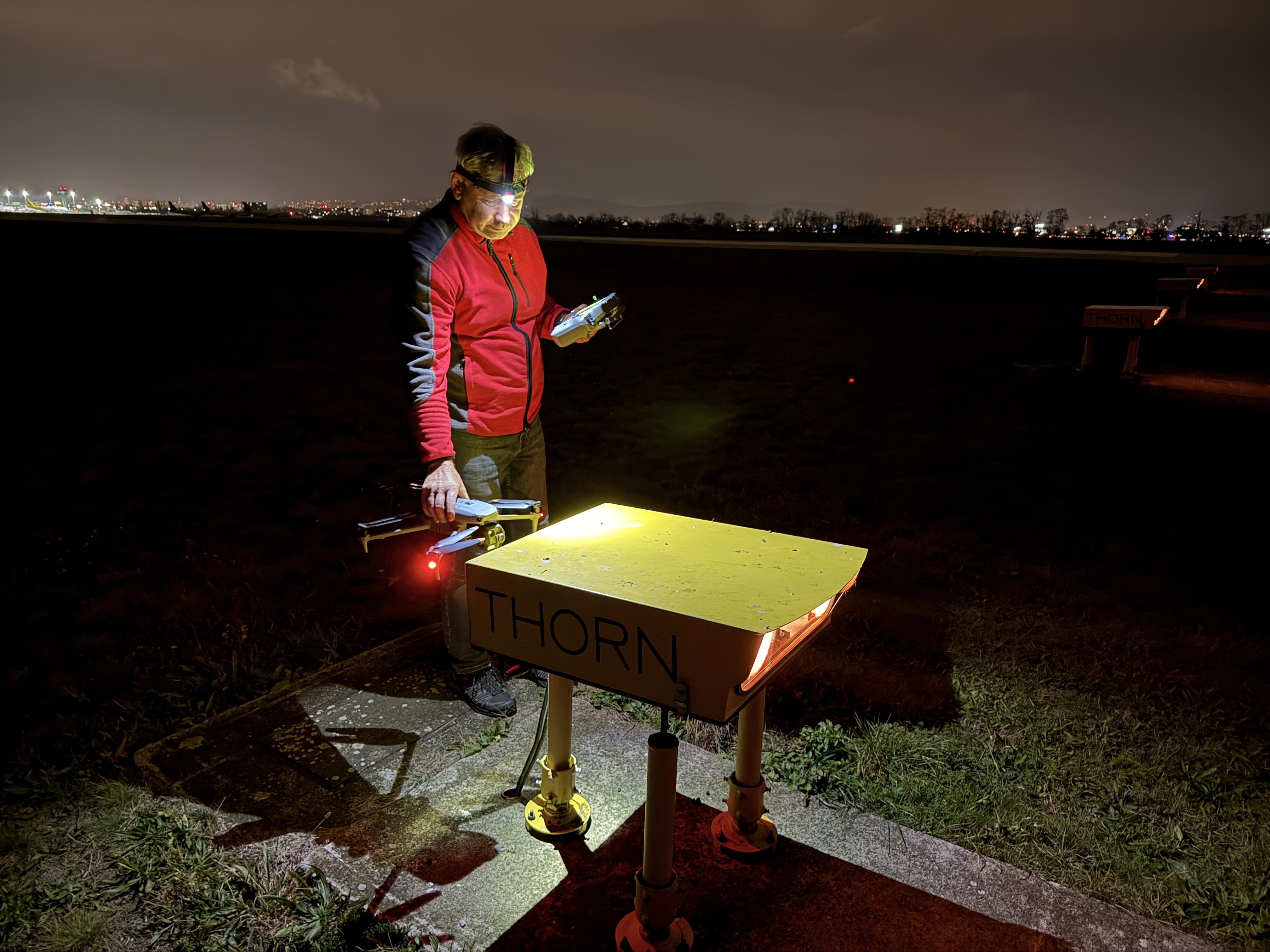
PAPI Lights Inspection and Calibration Check by Drone
Drone PAPI inspection. Each unit's transition angle, colour, intensity balance and surveyed position measured, with a same-day protocol to ICAO, EASA…
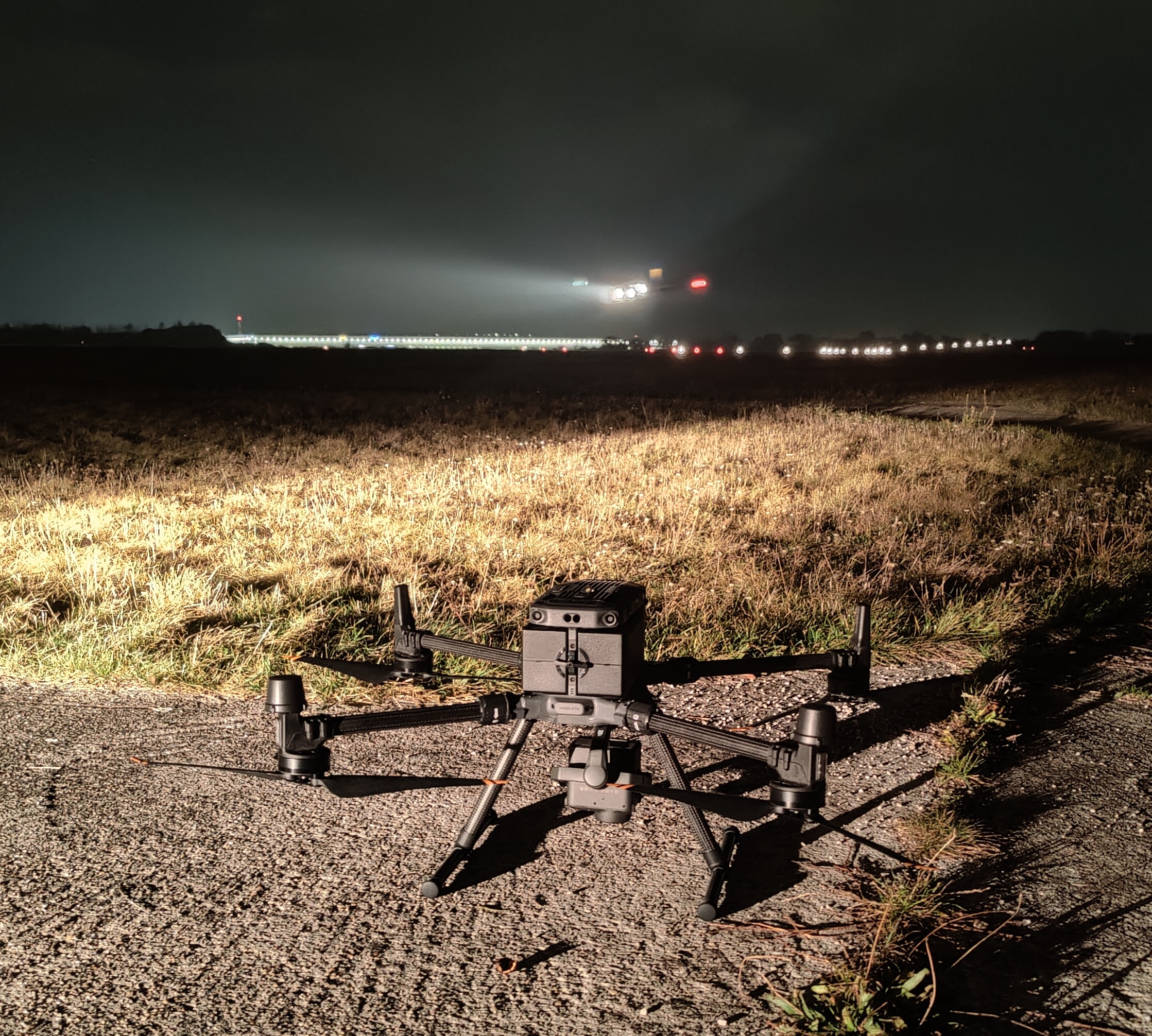
Drone Airport Inspection: Method and Limits
How a drone inspects an aerodrome between aircraft movements: the mission profile, RTK positioning, tower coordination, the evidence chain, and where…
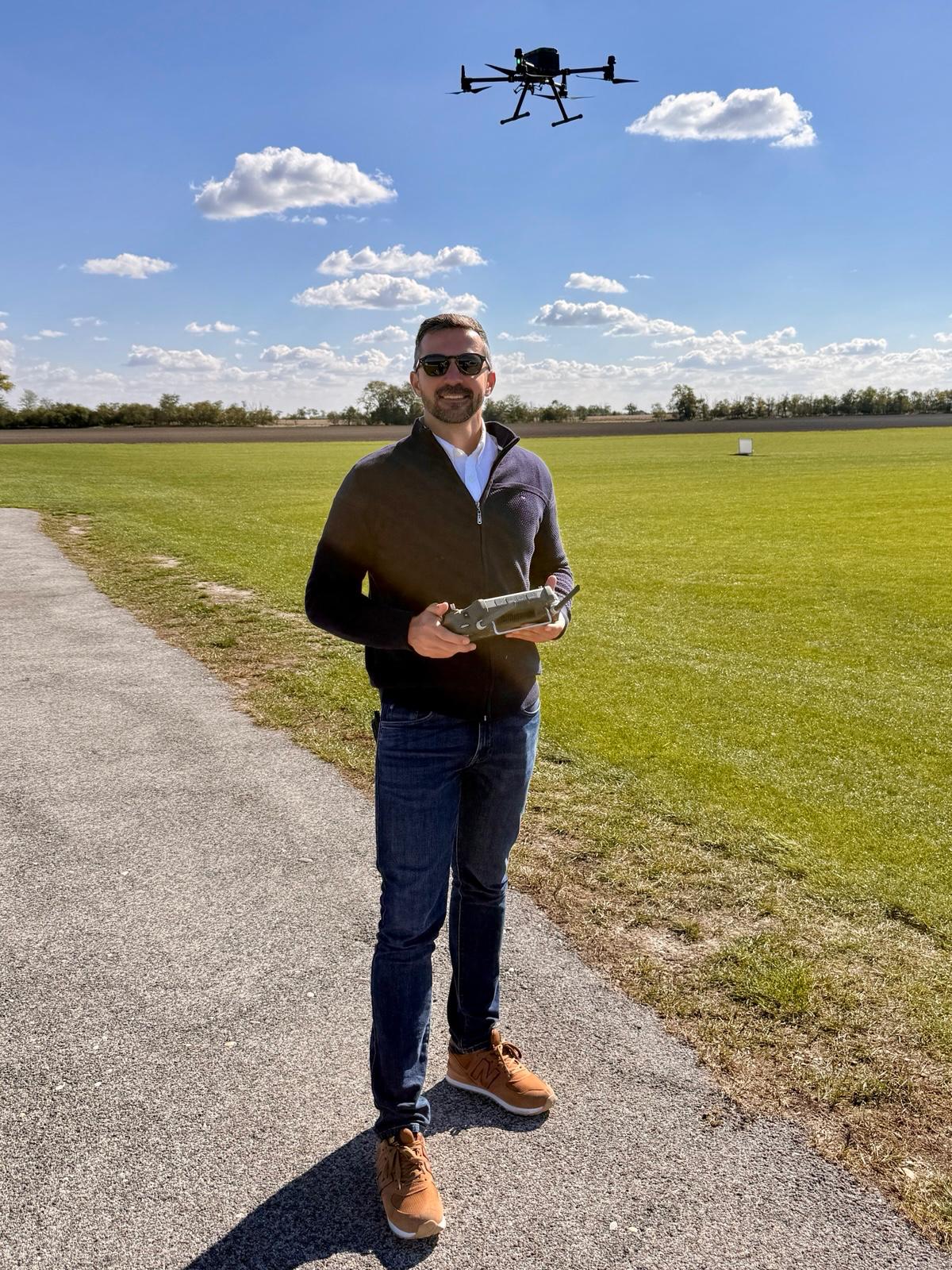
What a PAPI Inspection Actually Costs
What drives the cost of a drone-based airfield inspection, why we quote per airport instead of publishing a rate, and what the real comparison is.