MEHT: What Minimum Eye Height Over the Threshold Means for a PAPI
What MEHT means for a PAPI installation: the Annex 14 rule, how it sets the unit angles and the wing bar distance from the threshold, and the FAA equivalent.
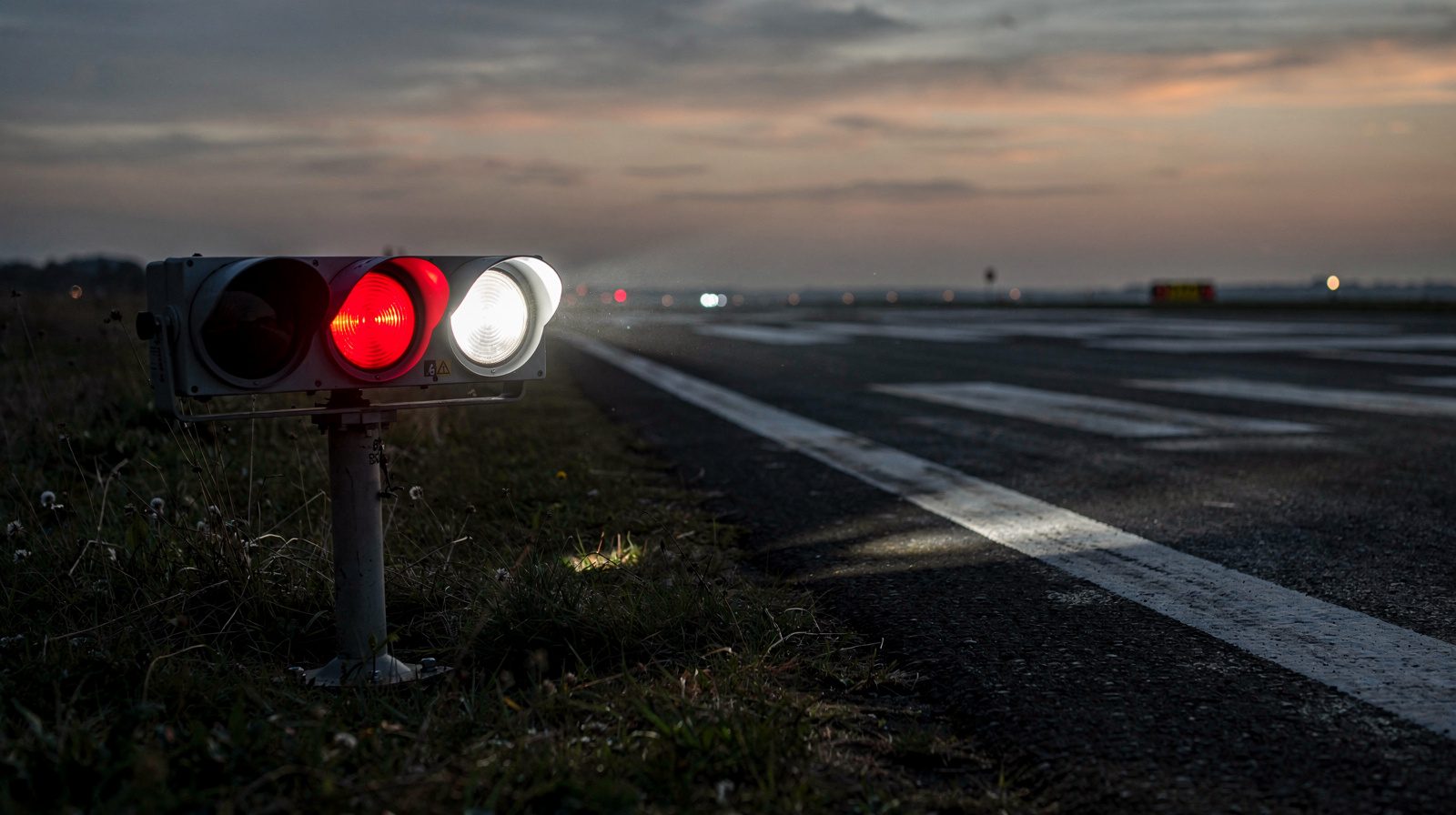 PAPI · WING BAR · THRESHOLD
MEHT is the minimum eye height over the threshold. It is the lowest height above the runway threshold at which a pilot sees the on-slope signal of a PAPI , two lights red and two white. ICAO Annex 14 sets it for a four-unit PAPI at angle B minus 2 arc-minutes, and it fixes where the wing bar stands.
What the Annex says
Annex 14 Volume I, paragraph 2.12, lists the data an aerodrome must make available for each visual approach slope indicator. Item e) is the minimum eye height over the threshold of the on-slope signal. For a PAPI it is angle B minus 2′, where B is the setting angle of the third unit from the runway. For a two-unit APAPI it is angle A minus 2′, the unit farther from the runway. The text says “shall”, so this is a Standard.
The EU lists the same item in GM1 ADR.OPS.A.005 under Regulation (EU) No 139/2014. That is guidance material, and it names the item without the arithmetic. The abbreviation is on the ICAO Doc 9157 Part 4 list. National AIPs carry it too, for example GEN 2.2 of the Slovak AIP, which marks with an asterisk the abbreviations that are different from or not in ICAO Doc 8400, and MEHT has none.
Why minus 2′? ICAO Doc 9157 Part 4 is guidance, and it explains that the 2′ accounts for the width of the transition zone over which the pilot sees a complete change from white to red. Separately, Annex 14 5.3.5.30 requires the colour transition to occur within no more than 3′ as seen from at least 300 m.
For a 3° slope, Annex 14 Figure 5-20 gives the setting angles 2°30′, 2°50′, 3°10′ and 3°30′ for units A to D, with D nearest the runway. So B is 2°50′ and the angle that defines MEHT is 2°48′, or 2.8°. Doc 9157 calls this angle M.
From the aircraft to a number
Annex 14 Table 5-2 groups aeroplanes by the eye-to-wheel height (EWH) in the approach configuration and gives a wheel clearance over the threshold for each group. Only aeroplanes that use the runway regularly count, and the most demanding one sets the group. Doc 9157 then adds the two numbers: MEHT is the EWH plus the desired or the minimum wheel clearance.
| Eye-to-wheel height | Desired wheel clearance | Minimum wheel clearance |
|---|---|---|
| up to but not including 3 m | 6 m | 3 m |
| 3 m up to but not including 5 m | 9 m | 4 m |
| 5 m up to but not including 8 m | 9 m | 5 m |
| 8 m up to but not including 14 m | 9 m | 6 m |
Annex 14 Volume I, Table 5-2. The 3 m minimum may fall to 1.5 m on runways used mainly by light-weight non-turbojet aeroplanes. CS-ADR-DSN Table M-1 repeats it with “should”.
The desired clearance is to be provided where practicable. The minimum may be used where an aeronautical study finds it acceptable.
Doc 9157 works one example. An A320 has an EWH of 7.25 m on a 3° approach, which puts it in the 5 m to 8 m group. With the desired 9 m clearance, MEHT is 16.25 m. With the minimum 5 m, it is 12.25 m. If the designer uses the top of the group, 8 m, the figures become 17 m and 13 m. Doc 9157 notes that the EWH values are examples and the designer should ask the aircraft manufacturer.
How MEHT sets the siting
Annex 14 Figure 5-19, note a), says that on a runway without an ILS the distance D1 from the threshold to the wing bar must be calculated so that the lowest height at which a pilot sees a correct indication gives the Table 5-2 wheel clearance for the most demanding aeroplane. Doc 9157 gives the method. On level ground, D1 is the MEHT divided by the tangent of angle M. For the example above, 16.25 m divided by tan 2.8° gives 332.26 m, and 347.6 m with the 17 m figure. Note c) adds that more wheel clearance for specific aircraft is achieved by increasing D1.
Four things change the result.
- Ground height. Note d) says D1 is adjusted for the difference in elevation between the lens centres and the threshold. In the Doc 9157 example the lens sat 3.14 m above the threshold, so the unit moved 64.20 m toward the threshold, from 332.26 m to 268.06 m.
- An ILS. Under note b), D1 is the distance from the threshold to the effective origin of the glide path plus a correction for eye-to-antenna height. Even then the wheel clearance may not fall below column 3 of Table 5-2. The ILS glide path is then the reference for the wing bar.
- A displaced threshold. Footnote d) of Table 5-2 requires that when a reduced wheel clearance is provided at a displaced threshold , the desired clearance is still available when an aeroplane at the top end of the chosen height group overflies the extremity of the runway.
- The angle itself. Since MEHT is D1 times tan M, an aiming error becomes a height error. At 332 m, one arc-minute is about 0.1 m (our arithmetic from the example), so a unit aimed 3′ low gives a MEHT roughly 0.3 m lower.
How MEHT sets the setting angles
The slope comes first. Annex 14 5.3.5.36 and 5.3.5.37 require a slope suitable for the aeroplanes using the approach, and as close as possible to the ILS glide path where there is one. The slope is (B + C) ÷ 2, and the units are spread around it. Doc 9157 Table 8-2 gives the differential settings found satisfactory.
| Approach angle | Differential setting, PAPI |
|---|---|
| 2° to 4° | 20′ |
| 4° to 7° | 30′ |
| over 7° | 1° |
ICAO Doc 9157 Part 4, Table 8-2. Guidance.
The sector width feeds back into M. A 30′ on-slope sector, which the Annex mentions for harmonising with the ILS closer to the threshold, gives setting angles 2°25′, 2°45′, 3°15′ and 3°35′ for a 3° slope. Doc 9157 then gives M as 2°43′. For the same 16.25 m MEHT, D1 grows from 332 m to about 342 m (our arithmetic).
Obstacles come in at the other end. Annex 14 5.3.5.38 requires that a pilot seeing one white and three reds clears all objects in the approach area by a safe margin. The slope of the obstacle protection surface for a PAPI is the A setting angle minus 0.57° (Table 5-3, which gives no PAPI slope for a non-instrument runway of code number 1). When an object penetrates it, 5.3.5.46 lists the options, among them raising the slope or displacing the system upwind of the threshold, which reduces the operational landing distance. Either one changes MEHT, so the published figure has to follow.
The FAA does it with TCH
AC 150/5340-30J does not use the term MEHT. It uses the threshold crossing height (TCH), the height of the lowest on-course signal directly above the intersection of the runway centreline and the threshold (7.5.4.5). The siting equation has the same shape, D1 = TCH × cotangent of the lowest on-course angle (7.5.4.3.1).
The conventions differ. The FAA takes the lowest on-course angle as the third unit, 10′ below the glide path, so 2°50′ on a 3° path, with no 2′ allowance. For height group 2 and a TCH of 45 ft, the circular computes D1 as 909.26 ft. An FAA TCH is not an ICAO MEHT, and the instrument threshold crossing height of an approach is a third quantity again.
| Height group | Cockpit-to-wheel height | Visual TCH |
|---|---|---|
| 1 | 10 ft (3 m) or less | 40 ft (+5, −20) |
| 2 | 15 ft (4.5 m) | 45 ft (+5, −20) |
| 3 | 20 ft (6 m) | 50 ft (+5, −15) |
| 4 | over 25 ft (7.6 m) | 75 ft (+5, −15) |
FAA AC 150/5340-30J, Table 7-1. Guidance in general, mandatory on projects funded through AIP grants or PFC revenue.
What this means for an inspection
MEHT is not measured directly. It follows from two things an inspection can check: the setting angle of unit B and where the units stand against the threshold. A moved unit, a re-aimed unit or a regraded verge each change one of the inputs, so any of them is a reason to check the published figure again.
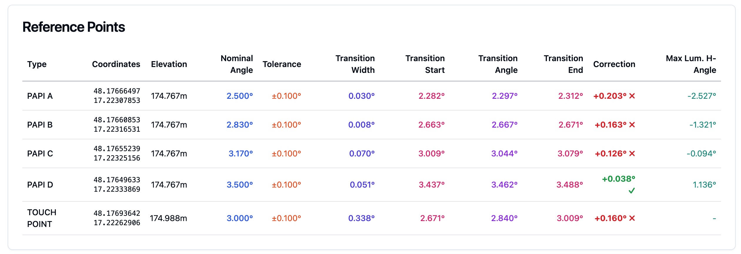
Our PAPI inspection measures the transition angle of every unit and its surveyed position. The protocol has a row for minimum eye height, which carries the value published for the runway. We do not set that value. The aerodrome derives it from the design data above.
Frequently Asked Questions
- What does MEHT mean for a PAPI installation?
- MEHT is the minimum eye height over the threshold, the lowest height at which a pilot sees the on-slope signal of the PAPI. The designer uses it to place the wing bar, because the distance from the threshold is the MEHT divided by the tangent of angle M. The aerodrome publishes the value for each runway.
- How is MEHT calculated for a PAPI?
- Annex 14 gives the published value as setting angle B minus 2 arc-minutes, where B is the third unit from the runway. The design height behind it is the pilot's eye-to-wheel height plus the wheel clearance over the threshold, from Annex 14 Table 5-2. Doc 9157 Part 4 works the method.
- What is a typical MEHT value?
- ICAO Doc 9157 works one example. An A320 with an eye-to-wheel height of 7.25 m gets a MEHT of 16.25 m with the desired 9 m wheel clearance and 12.25 m with the minimum 5 m. The eye-to-wheel values are examples, so the designer asks the aircraft manufacturer.
- Why does MEHT change the position of the PAPI?
- Because the wing bar distance D1 on level ground is the MEHT divided by the tangent of angle M. A higher MEHT, which gives more wheel clearance, puts the wing bar farther from the threshold. Ground height, an ILS and a displaced threshold each adjust the result.
- Does the FAA use MEHT for a PAPI?
- No. FAA AC 150/5340-30J uses the threshold crossing height (TCH) and does not use the term MEHT. The siting equation has the same shape, D1 equals TCH times the cotangent of the lowest on-course angle, but an FAA TCH is not an ICAO MEHT.
References
- icao-annex-14-vol-1
- Annex 14 to the Convention on International Civil Aviation, Volume I, Aerodrome Design and Operations, 9th edition, July 2022 (English text, copy hosted by the Swiss Federal Office of Civil Aviation) International Civil Aviation Organization
- icao-doc-9157-part-4
- Aerodrome Design Manual, Part 4: Visual Aids (Doc 9157), Fifth Edition, 2021, with Amendment No. 1 (English text, copy hosted by the Swiss Federal Office of Civil Aviation) International Civil Aviation Organization
- easa-ear-aerodromes
- Easy Access Rules for Aerodromes (Regulation (EU) No 139/2014), including CS-ADR-DSN Issue 7 European Union Aviation Safety Agency
- faa-ac-150-5340-30j
- AC 150/5340-30J, Design and Installation Details for Airport Visual Aids Federal Aviation Administration
- sk-aip-gen-2-2
- AIP Slovak Republic, GEN 2.2 Abbreviations used in AIS publications Letové prevádzkové služby Slovenskej republiky
Founded by flight-inspection veterans who spent decades measuring PAPI lights for aviation authorities across Europe.
Learn more
Related terms
03 TERMSMinimum Eye Height over Threshold (MEHT)
MEHT is the lowest pilot eye height that gives an on-slope PAPI signal at the threshold. How it is set, the formula, a worked example and the FAA equivalent.
PAPI Approach Slope and Elevation Setting
The PAPI approach slope and elevation setting are the approach angle a PAPI shows and the angle of each unit. Setting angles for 3 degrees, tolerance, how they are measured, and drones.
Color Transition
A colour transition is the boundary in the beam of an approach slope light unit where white changes to red. How a PAPI forms its signals, how sharp the transition must be, how VASI and tri-colour systems differ, and what inspection checks.
Further reading
03 ARTICLES
How PAPI Transition Angles Are Verified in the Field
How to verify PAPI transition angles in the field: clinometer and ground checks, flight checks and drone measurement, with the ICAO, EASA and FAA…
What ICAO Annex 14 Actually Requires of Your PAPI
The tolerances behind a PAPI protocol, what an authority looks for in the evidence, and how often the system has to be verified to stay certifiable.

What a PAPI Calibration Tender Should Include
What a PAPI verification tender should include: scope, method, tolerances, report contents and frequency, with the EU, ICAO and FAA source for each.…