How PAPI Transition Angles Are Verified in the Field
How to verify PAPI transition angles in the field: clinometer and ground checks, flight checks and drone measurement, with the ICAO, EASA and FAA rules.
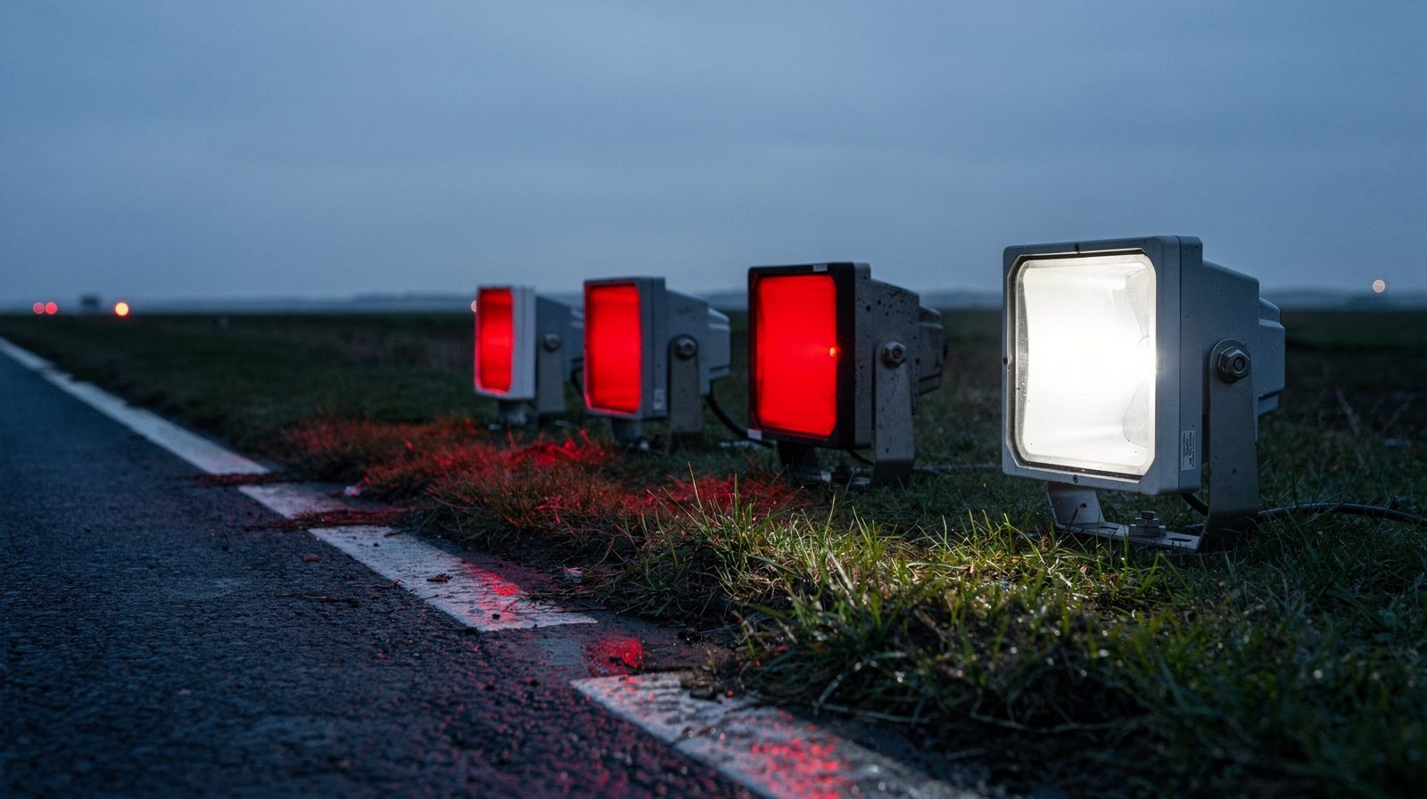
 PAPI · WING BAR · DUSK
You verify a PAPI transition angle in the field by finding the height at which each unit changes from red to white, then turning that height and the distance to the unit into an angle above the horizontal. Ground aiming checks, flight checks and drone measurements all do this, and each sees something different.
What is being verified
A PAPI is a wing bar of four units. Each light box throws a beam that is red in its lower part and white in its upper part, and the setting angle is the elevation of the line between them. Annex 14 requires each unit to be adjustable so that the lower limit of the white part can be fixed anywhere from 1°30′ to at least 4°30′ above the horizontal (5.3.5.34, a Standard). For a 3 degree approach the four units are set at 2°30′, 2°50′, 3°10′ and 3°30′, from the unit farthest from the runway to the nearest. CS-ADR-DSN Figure M-5 shows those angles and Doc 9157 Table 8-1 lists the same four. A note on Figure M-5 gives 2°25′, 2°45′, 3°15′ and 3°35′ where the on-course sector is widened from 20′ to 30′ to bring the PAPI closer to the ILS glide path.
A pilot on the slope sees the two nearest units red and the two farthest white (Annex 14 5.3.5.26). So the angle that counts is where the colour changes in the air in front of the unit, not where the housing points.
The three minutes that are not a tolerance
The figure people quote for a PAPI is 3 minutes of arc. In the sources it limits something else. Annex 14 5.3.5.30 says the change from red to white must appear, to an observer at not less than 300 m, to occur within a vertical angle of not more than 3 minutes of arc. CS-ADR-DSN.M.645 carries the same wording. That is the depth of the transition. It does not say how far a unit may be from its design angle.
The text of Annex 14 and CS-ADR-DSN.M.650 that we searched gives no tolerance on the setting angle. The limits that exist sit in lower-ranking material, and they differ.
| Source | Status | What it limits | Figure |
|---|---|---|---|
| Annex 14, 5.3.5.30 | Standard | Depth of the red to white transition seen from 300 m or more | Within 3 minutes of arc |
| CS-ADR-DSN.M.645(c)(2)(i) | EASA certification specification, worded with should | Same transition limit | Within 3 minutes of arc |
| AMC1 to ADR.OPS.C.015(b) and (f), point (b) | EASA acceptable means of compliance | Alignment errors of visual approach slope indicator systems found in ground checks | Errors in excess of 1 minute of arc should be corrected |
| Doc 9157, 8.3.25 and 8.3.33 | ICAO guidance | Accuracy of the ground survey and of the image analysis method | About 3 minutes and better than 1 minute |
| AC 150/5340-26C, Table A-7 | FAA recommended guidance, mandatory on AIP and PFC funded projects | Vertical aiming of each unit against its standard angle, for a 3 degree path unless a local standard applies | ±2 minutes initial, ±6 minutes operating |
The EU rule itself, ADR.OPS.C.015(b), requires a maintenance programme that keeps the individual lights serviceable. For a runway with visual approach slope indicators its objective is that all units are serviceable, and it sets no setting angle tolerance. The one minute of arc sits in the AMC, which speaks of visual approach slope indicator systems and names the PAPI in the same point.
Ground aiming checks
The first check is at the unit. A PAPI is typically supplied with a clinometer, and the technician reads each box’s aiming angle against its own structure (Doc 9157 8.3.21 and 8.3.23). The inclinometer is also the tool that resets a box. The FAA asks for a monthly check of aiming with the PAPI aiming instrument, with the angle and the date written in a maintenance log. It adds that aiming should be checked more often when the soil freezes, thaws or changes moisture, especially clay (AC 150/5340-26C, 5.7.1.2 point h).
A clinometer has a blind spot. It measures aim against the housing, not the projected beam, and the optical axis can differ from the mechanical one after damage in transport or a blow from snow-clearing exhaust (8.3.32). The manual therefore asks for a ground check by a method independent of the clinometer, and says that check is not a calibration technique. If it finds a discrepancy, the box is reset with the clinometer (8.3.24).
Doc 9157 describes three ground methods.
- Ground survey (8.3.25 to 8.3.30). A theodolite is levelled on top of the unit and an observer slides an engineer’s square up a surveyor’s rod until the signal turns white, then down until it turns red. The midpoint of the two heights gives the transition, and the angle is read from the theodolite. The manual puts the accuracy at about 3 minutes of arc and warns that the observer and too intense a setting both bias the readings.
- Image analysis (8.3.32 to 8.3.35). A camera on a tripod 10 to 15 m from the unit finds the centre of the transition, referenced to an electronic gravity platform. The manual gives an accuracy better than 1 minute of arc and says some States allow it as a substitute for flight checks.
- Checkboard (8.3.36 and 8.3.37). A screen on a rod stands 20 m ahead of the unit, marked in 1 minute steps over 5 minutes either side of a zero line. The transition should fall on the zero line.
Doc 9157 is guidance. Annex 14 points to Part 4 only in Notes, such as the one after 5.3.5.32, and Notes are not part of the Standards. Each of these is therefore a method a State may adopt, not one it must.
Flight checks
A flight check sees the system the way the pilot does. The EU AMC asks for a flight check of the approach, runway and taxiway lighting, the slope indicators, the aerodrome beacon and the intensity control at regular intervals, at least yearly. It also asks for special flight checks after major maintenance or changes and before new systems are commissioned (AMC1 to ADR.OPS.C.015(b) and (f), point (d)). The guidance material adds that on precision approach runways the slope indicators are also checked for correct approach slope and for compatibility with the non-visual aids.
Doc 9157 8.3.42 says the competent authority should flight-inspect a new installation. The inspection covers range, brilliancy control, setting angles and compatibility with the precision instrument glide path. For the angles the manual’s own words are “to ensure that there is no gross misalignment”. The United States works differently. AC 150/5340-30J asks for a commissioning flight inspection of a new visual glideslope indicator with an instrument procedure on the runway, and says there is no periodic inspection requirement for these facilities. Confirmation of safe operation should be done alongside other flight inspections of the same runway (7.7.6.6.4).
Drone measurement
Doc 9157 8.3.43 says an unmanned aircraft system may be used as an alternative method for measuring PAPI settings. The aircraft is positioned at least 300 m downwind of the system. Vertical scanning finds h1 and h2, the upper and lower limits of the transition zone, and the setting angle follows from the arctangent of (h1 + h2) divided by twice the horizontal distance d (8.3.44). Horizontal scanning finds the lateral limits of the beam by noting when units D and A disappear (8.3.45). The manual says a real time kinematic base station is necessary for high dimensional precision, so the positioning rests on RTK .
The reason the position matters is plain geometry, not a figure from the manual. At 300 m, 1 minute of arc is a height difference of about 8.7 cm and 3 minutes is about 26 cm.
Two cautions come with the method. The manual asks for a visible spectrum camera or sensor that is operationally validated against perceived total image quality, and says the method may need special authorization from the State (8.3.46). It also gives no accuracy figure for the unmanned method, so the number has to come from the provider’s own measurement uncertainty statement and the evidence behind it. In 2025 Kazakhstan told the ICAO Assembly that existing ICAO material has no procedures, performance criteria or safety parameters specific to unmanned systems (A42-WP/343, 2.2.1). That is one State’s view in an information paper, not an ICAO position. Whether regulators accept drone PAPI checks is a separate question, answered authority by authority.
Putting the methods together
The methods answer different questions. The clinometer says how the box is set. An independent ground method says where its beam goes. A flight check says what the pilot sees. A drone measurement reports the angle of every unit from the approach, with the heights and the distance behind each figure, so a reviewer can recompute it.
Events call for a new check whatever the interval says. The EU AMC and its guidance material name unstable ground, frost, heavy rain, drought and an aircraft occurrence. The FAA adds contact with mowing equipment. TarmacView’s PAPI inspection is a drone measurement of PAPI settings. It reports a measured angle per unit, and the authority decides how that evidence enters the maintenance programme. For what to do when a unit proves out of tolerance, see PAPI out of tolerance: confirm, re-aim, re-check .
Frequently Asked Questions
- How do you verify PAPI transition angles in the field?
- You find the height at which each unit changes from red to white and turn it into an angle. Doc 9157 describes a ground survey with a theodolite, image analysis from a tripod and a checkboard. A flight check and a drone measurement read the angle from the approach.
- What is the ICAO tolerance for PAPI setting angles?
- The Annex 14 text we searched gives none. Annex 14 5.3.5.30 limits the depth of the red to white transition to 3 minutes of arc seen from 300 m, which is not a setting tolerance. The EU AMC says errors above 1 minute of arc should be corrected, and FAA AC 150/5340-26C gives plus or minus 2 minutes initial and 6 minutes operating.
- What are the alternatives to a flight inspection aircraft for checking PAPI?
- Doc 9157 lists ground methods and an unmanned aircraft method. The ground methods are a theodolite survey, image analysis and a checkboard, and the manual says some States allow image analysis in place of flight checks. A State decides whether any of them replaces a flight check.
- How accurate is a drone PAPI measurement compared with an aircraft flight inspection?
- No ICAO text we read gives an accuracy figure for the drone method, so there is nothing to compare against an aircraft. Doc 9157 8.3.44 says a real time kinematic base station is needed for high precision. The figure has to come from the provider's measurement uncertainty statement.
- Does a clinometer check prove the PAPI is aimed correctly?
- No. A clinometer measures the box against its own structure, and the optical axis can shift after transport damage or snow blower exhaust (Doc 9157 8.3.32). The manual asks for an independent ground check, and says that check is not a calibration technique.
References
- easa-ear-aerodromes
- Easy Access Rules for Aerodromes (Regulation (EU) No 139/2014) European Union Aviation Safety Agency
- icao-annex-14-vol-i
- Annex 14 to the Convention on International Civil Aviation, Aerodromes, Volume I, Aerodrome Design and Operations, Ninth Edition, July 2022 (English text, copy hosted by the Swiss Federal Office of Civil Aviation) International Civil Aviation Organization
- icao-doc-9157-part-4
- Aerodrome Design Manual, Part 4: Visual Aids (Doc 9157), Fifth Edition, 2021, with Amendment No. 1 and Corrigendum No. 1 (English text, copy hosted by the Swiss Federal Office of Civil Aviation) International Civil Aviation Organization
- faa-ac-150-5340-26c
- AC 150/5340-26C, Maintenance of Airport Visual Aid Facilities Federal Aviation Administration
- faa-ac-150-5340-30j
- AC 150/5340-30J, Design and Installation Details for Airport Visual Aids Federal Aviation Administration
- icao-a42-wp-343
- A42-WP/343, Integrating drone technologies into visual aid flight checks: towards ICAO harmonization (Kazakhstan, information paper, 29/7/25) International Civil Aviation Organization
Founded by flight-inspection veterans who spent decades measuring PAPI lights for aviation authorities across Europe.
Learn more
Related terms
03 TERMSColor Transition
A colour transition is the boundary in the beam of an approach slope light unit where white changes to red. How a PAPI forms its signals, how sharp the transition must be, how VASI and tri-colour systems differ, and what inspection checks.
PAPI Approach Slope and Elevation Setting
The PAPI approach slope and elevation setting are the approach angle a PAPI shows and the angle of each unit. Setting angles for 3 degrees, tolerance, how they are measured, and drones.
Light Unit
A light unit is one light assembly of an airfield lighting system, such as one unit of a PAPI. Units per system, PAPI aiming, spacing, serviceability and LED reporting.
Further reading
03 ARTICLES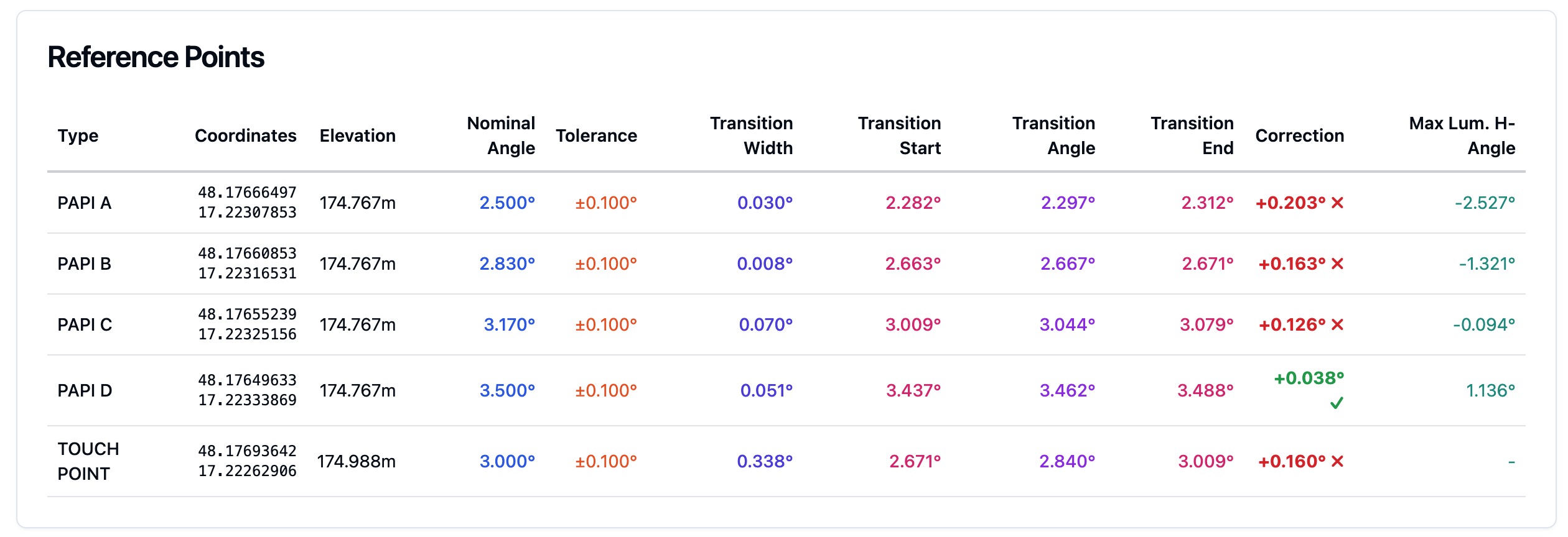
What ICAO Annex 14 Actually Requires of Your PAPI
The tolerances behind a PAPI protocol, what an authority looks for in the evidence, and how often the system has to be verified to stay certifiable.
What a PAPI Calibration Tender Should Include
What a PAPI verification tender should include: scope, method, tolerances, report contents and frequency, with the EU, ICAO and FAA source for each.…
PAPI Out of Tolerance: What the Rules Say and When a NOTAM Is Due
What happens if a PAPI is out of tolerance and when a NOTAM is due: the EASA, ICAO, FAA and UK CAA rules on error limits, unserviceability and…