FAA AC 150/5345-28: Precision Approach Path Indicator Systems
What FAA AC 150/5345-28H specifies for PAPI equipment: L-880 and L-881 types, red-white transition, light output, aiming tool and tilt cut-off, versus EASA.
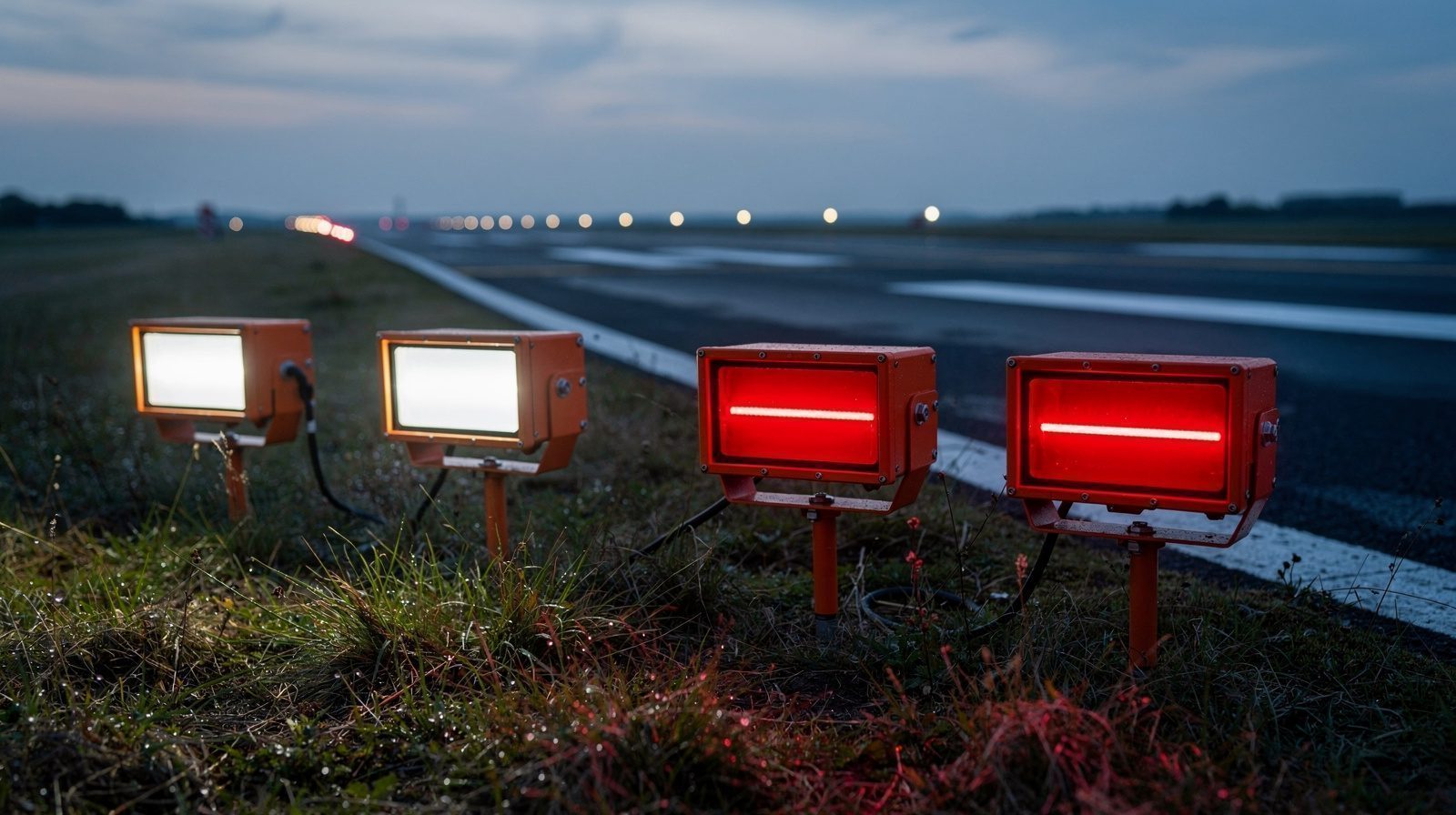
- 01 Paragraph 4 makes the circular mandatory only for projects funded through the Airport Improvement Program or Passenger Facility Charges. Otherwise the FAA recommends it as one acceptable means of meeting 14 CFR Part 139.
- 02 Type L-880 is a system of four light units and type L-881 a system of two. Style A is voltage powered and Style B runs on a series lighting circuit of 2.8 to 6.6 amperes.
- 03 Viewed at 1000 feet, the red-white transition must fall within 3 minutes of arc at the beam centre and 5 minutes at the beam edges, and the transition band must stay straight and flat within 3 minutes.
- 04 The aiming tool covers 2 to 8 degrees in 10 minute steps with a repeatable accuracy of 3 minutes, and a unit tilted out of its preset angle must switch every lamp in the system off.
- 05 The circular sets qualification tests and production tests for the equipment. It sets no tolerance for an installed unit in service and never mentions drones or flight inspection.
On this page · 12 sections
No FAA text read for this page accepts a drone check in place of a PAPI flight inspection. AC 150/5345-28H never mentions drones. The FAA says drones cannot be the only means of Part 139 self-inspections and may only add to them. Its flight inspection guide still sets when a PAPI needs an aircraft check.
A PAPI is a piece of equipment before it is an approach aid. In the United States one short advisory circular says what that equipment has to be. AC 150/5345-28H was issued on 29 July 2019, initiated by AAS-100 and signed by the FAA Director of Airport Safety and Standards, and cancels the 2011 edition, 28G. The FAA record lists it as active, and no later revision turned up on 23 October 2026. It is a specification for the unit, its beam, its aiming tool and its tests. Where a unit goes and where it points are in other circulars.
What the circular is, and who it binds
Paragraph 1 says the circular “contains the Federal Aviation Administration (FAA) standards for the Precision Approach Path Indicator (PAPI) systems.” Paragraph 4 sets the status. The FAA recommends the guidance and specifications. The circular “does not constitute a regulation and is not mandatory”, and it is one acceptable means of meeting 14 CFR Part 139. The lighting configurations in it are described as acceptable for the lighting requirements of section 139.311. Use is mandatory for all projects funded with federal grant money through the Airport Improvement Program (AIP) and with Passenger Facility Charges (PFC) revenue, through Grant Assurance No. 34 and PFC Assurance No. 9.
Paragraph 2 gives it a second job. Six months after the issue date, only equipment qualified to these specifications is listed under AC 150/5345-53, the airport lighting equipment certification program. So the “must” statements in chapters 3 and 4 are written to the manufacturer, who has to pass the tests.
AC 150/5345-28H at a glance
- Issuer
- Federal Aviation Administration, initiated by AAS-100. Dated 29 July 2019, cancels 28G of 29 September 2011.
- Status
- Recommended guidance. Mandatory for AIP-funded and PFC-funded projects through Grant Assurance No. 34 and PFC Assurance No. 9 (paragraph 4).
- Types
- L-880 with four light units, L-881 with two light units (paragraph 1.1.1).
- Styles and classes
- Style A voltage powered, Style B series circuit. Class I from minus 35 to 55 degrees Celsius, Class II from minus 55 to 55 degrees Celsius (paragraphs 1.1.2 and 1.1.3).
- Transition
- Within 3 minutes of arc at the beam centre and 5 at the beam edges, viewed at 1000 feet (paragraph 3.2.1 item 3).
- Aiming range
- Beam centre adjustable at any elevation from 2 to 8 degrees, aiming tool graduated in 10 minute steps with 3 minute repeatable accuracy (paragraphs 3.2.4.1 and 3.2.4.1.1).
- Tilt cut-off
- All lamps switch off when a unit is lowered more than one quarter degree or raised more than one half degree, after a delay of 10 to 30 seconds (paragraph 3.2.5).
- Tests
- Climate, wind, frangibility, photometric, rigidity, aiming device and operational tests for qualification, plus a production test of light output and aiming accuracy (chapters 4 and 5).
Types, styles and classes
Paragraph 1.1 sorts every system three ways. The type is the number of units. An L-880 has four, and an L-881 has two, which matches the unit count of the PAPI and APAPI in Annex 14 sections 5.3.5.24 and 5.3.5.25. The style is the power source. Style A systems run from voltage, from any standard utility single-phase service below 600 volts, with a power control unit that may sit in its own cabinet or inside a light box (paragraphs 3.3.1 and 3.3.3). Style B systems run from a series lighting circuit with a current of 2.8 to 6.6 amperes and take their power through an isolation transformer (paragraph 3.4). The regulator and the isolation transformer are not supplied with the PAPI (note to paragraph 3.4, which names the L-828 as the regulator example). The class is the climate. Class I operates from minus 35 to 55 degrees Celsius and Class II from minus 55 to 55 degrees Celsius, both in humidity up to 100 percent and in wind up to 100 miles per hour (paragraph 3.1).
Four options can be added. They are a lamp socket bypass for Style B, an alternate harness that combines several transformer outputs, a horizontal beam coverage adjustment and a lamp monitor. The lamp monitor in paragraph 3.5 is described as an optional go/no go output, nothing finer.
The red-white transition
The circular and the other two texts use different names for the same thing. Annex 14 and CS-ADR-DSN call the change from red to white the transition sector. The FAA calls it the transition band, and in paragraph 3.2.4.1 it is also what the circular means by the centre of the beam.
Paragraph 3.2.1 sets four conditions on it. The beam is split horizontally, with aviation white in the top sector and aviation red in the bottom sector. Viewed at 1000 feet (300 meters), the change from red to white must fall within 3 minutes of arc at the beam centre and within 5 minutes of arc at the beam edges. A line drawn through the centre of the transition band at plus 10, 0 and minus 10 degrees must be straight within 3 minutes of arc. The band must be flat within 3 minutes of arc.
Three minutes of arc is 0.05 degree. At 300 meters that is a little over 25 centimetres of height, which is arithmetic and not a figure from the circular.
Light distribution and colour
Paragraph 3.2.1 item 6 hands the intensity to Figure 3-1, which is drawn as isocandela contours from minus 10 to plus 10 degrees in azimuth. Read from the rendered page, the white half is labelled 30,000, 20,000, 14,000, 8,000 and 5,000 candela moving outward from the centre circle. The red half is labelled 15,000, 10,000, 7,000, 4,000 and 2,500 candela. At each contour the white value is twice the red. The figure does not say whether the values are minimums, so this page does not call them that. The text of 4.9 tests the pattern on one set of lamps and checks repeatability on two more.
Colour is separate. The white and red must meet SAE AS25050, paragraph 3.1. For LED units, FAA Engineering Brief 67 gives the white and red chromaticity coordinates, and for an incandescent unit the red may follow the same brief if the device and manual say so (paragraph 3.2.1 item 7). Lamps need a minimum rated life of 1000 hours and light sources must reach full intensity within 5 seconds of a cold start. A Style A system must also have a photoelectric control. Day mode is selected when illumination on a vertical surface facing north rises to between 50 and 60 foot-candles and night mode when it falls to between 25 and 35, with a delay of 45 to 75 seconds. Two night settings of roughly 5 and 20 percent of the day mode intensities adapt the unit to the airport’s ambient light (paragraphs 3.3.6 and 3.3.8).
The units must also keep the optics clear. Paragraph 3.2.2 requires a protective overhang or another method against rain and snow, and 28H updated the requirement that the unit prevent dew, frost and ice from accumulating on the lens, by a thermostatic heater or by the intrinsic heat of the lamps.
Aiming, tilt and horizontal coverage
Paragraph 3.2.4.1 asks for built-in adjustment of the beam centre at any elevation between 2 and 8 degrees. An aiming tool must be supplied that measures the vertical angle across the same range in increments of 10 minutes of arc, with a repeatable accuracy of 3 minutes of arc. The alternative in 3.2.4.1.2 is a unit factory calibrated to one angle the purchaser specifies, in which case the manufacturer must provide a way to check the calibration in the field to 3 minutes of arc. The 4.12 aiming device test checks the reading at one-degree intervals from 2 to 8 degrees.
Paragraph 3.2.4.1.3 was added in 28H. The design must allow the horizontal beam coverage to be modified for obstacles in the approach area, for example with baffles. Section 4.9 then requires the photometric test to be repeated with the full adjustment fitted, and the narrower beam must still meet the intensity requirements where it is unobstructed.
Paragraph 3.2.5 covers a unit that moves. All lamps in the system must be de-energised when one unit is lowered more than one quarter degree or raised more than one half degree from its preset angle. A delay of 10 to 30 seconds stops vibration from tripping it, and the sensing must fail safe, so a fault or loss of power also switches the PAPI off. The operational test in 4.13 includes this mechanism.
None of this tells an installer which angle to set. Paragraph 2.1 sends siting and installation to AC 150/5340-30. In its edition J, paragraph 7.5.4.6 and Table 7-2 set the four L-880 units, counting from the unit nearest the runway, 30 minutes above, 10 minutes above, 10 minutes below and 30 minutes below the pre-selected glide path. For height group 4 aircraft on an ILS runway the offsets are 35 and 15 minutes. The two L-881 units in Table 7-3 sit 15 minutes above and 15 minutes below. Paragraph 3.9 of the circular refers to AC 150/5340-26 for maintenance, which the maintenance circular page covers.
Qualification and production tests
Chapter 4 lists what a manufacturer must show. The equipment is run at 55 degrees Celsius for 4 hours, and held at minus 35 or minus 55 degrees Celsius for 24 hours depending on class. The wind-blown rain test uses 5.2 inches per hour for 30 minutes per side. The salt-fog test runs 48 hours with 48 hours of drying. A 100 mile per hour wind load, shown by tunnel or static test, must not displace the optical pattern more than the rigidity test allows. In that test a sand load of 15 pounds per square foot sits on the unit for 5 hours, and the beam pattern must stay within one quarter inch of its marks, projected on a surface 20 feet in front. The mounting legs must break away like the 2-inch frangible coupling in FAA drawing C-6046.
Chapter 5 asks for a production test procedure that verifies light output and aiming device accuracy on every unit, approved by the third-party certification body. The visual examination and operational test run on every production system.
How it compares with the EU and ICAO texts
In the EU the specification for a PAPI is CS-ADR-DSN, paragraphs M.645 to M.655, under Regulation (EU) No 139/2014. The CS paragraphs are written with “should”, and the EASA CS-ADR-DSN page sets out how they are applied. Annex 14 Volume I, section 5.3.5, gives the equivalent PAPI characteristics as Standards with “shall”, and the ICAO Annex 14 page places them. The Annex 14 paragraphs here were checked against the 9th edition of July 2022 as hosted by the Swiss FOCA. That copy lists Amendment 18, applicable 27 November 2025, in its amendment table, so check the current text before relying on a value.
What each text asks of a PAPI unit
| Topic | FAA AC 150/5345-28H | EASA CS-ADR-DSN Issue 7 | ICAO Annex 14 Vol I, 9th ed. |
|---|---|---|---|
| Status of the text | Recommended guidance, mandatory for AIP and PFC funded projects (paragraph 4) | Certification specification, written with should (M.645) | Standards, written with shall (5.3.5.24 to 5.3.5.41) |
| Units in the system | L-880 four units, L-881 two units (1.1.1) | PAPI four units, APAPI two units (M.645(b)) | PAPI four units, APAPI two units (5.3.5.24, 5.3.5.25) |
| Red-white transition | Within 3 minutes at the beam centre and 5 at the edges, viewed at 1000 feet (3.2.1) | Within 3 minutes for an observer at not less than 300 meters (M.645(c)(2)) | Within 3 minutes for an observer at not less than 300 meters (5.3.5.30) |
| Elevation adjustment | Beam centre at any elevation from 2 to 8 degrees (3.2.4.1) | Lower limit of the white part from 1 degree 30 minutes to at least 4 degrees 30 minutes (M.645(c)(4)) | Lower limit of the white part from 1 degree 30 minutes to at least 4 degrees 30 minutes (5.3.5.34) |
| Intensity | Figure 3-1, red 15,000, 10,000, 7,000, 4,000 and 2,500 cd, white twice the red | Figure U-26, minimum red 15,000, 10,000, 7,000 and 4,000 cd, white 2 to 6.5 times the red | Figure A2-23, minimum red 15,000, 10,000, 7,000 and 4,000 cd, white 2 to 6.5 times the red |
| Colour | SAE AS25050, Engineering Brief 67 for LED (3.2.1) | CS ADR-DSN.U.930, red with Y not above 0.320 (M.645(c)(2)) | Red with Y not above 0.320 (5.3.5.31) |
| Aiming tool and tilt cut-off | Aiming tool to 3 minutes of arc, all lamps off on tilt (3.2.4.1.1, 3.2.5) | No tilt provision in M.645 to M.650 | No tilt provision in 5.3.5.24 to 5.3.5.41 |
The FAA figure adds an outermost 2,500 candela red contour that the other two do not show, and it fixes the white at twice the red where the other two allow a range. The circular says nothing about acceptance outside the United States.
What the FAA says about drone checks and flight inspection
Three FAA documents bear on the question. None of them accepts a drone PAPI check as a substitute for a flight inspection.
- FAA unmanned aircraft page for airport operations. It answers whether a drone can complete required Part 139 self-inspections. UAS cannot be the only means of performing them at this time. An operator may use UAS as an additional tool but must still conduct the self-inspections defined in its Airport Certification Manual. The FAA says research is ongoing and that sUAS must be supplemented by traditional methods until standards are formalised. This is about self-inspection, not about flight inspection.
- Flight Inspection Commissioning Requirements Decision Guide (Flight Program Operations, issued 25 February 2026). A new or relocated VGSI or PAPI for a runway with an IFR procedure needs a commissioning flight inspection. A change such as a 2-box to 4-box system or a new published angle may need one. It is mandatory where the PAPI mitigates an unlit 20:1 obstacle penetration. The guide lists the VGSI angle criterion as within plus or minus 0.2 degrees of the desired angle. It says it sets no regulatory requirement, and it does not mention drones.
- FAA Order 8200.1D, United States Standard Flight Inspection Manual (April 2015 edition, the one read here). For a VGSI the flight inspector checks the glidepath angle by flying the approach. In a 4-box PAPI the angle of all four light boxes is measured and reported. The text has no word on unmanned aircraft.
So the FAA answer, from the text read, is no. A drone result may inform an airport’s own checks and maintenance, but nothing opened gives it the standing of a flight inspection. Whether a given use is accepted is for the airport and its FAA Airports District Office.
What a PAPI light unit, a cutoff angle and light emissions are
A light unit is one light box of the system. ICAO Annex 14 paragraph 5.3.5.24 describes a PAPI as a wing bar of four sharp transition units, equally spaced, and an APAPI (5.3.5.25) as two. AC 150/5345-28H names these the L-880 and L-881. A pilot on the approach slope sees the two units nearest the runway as red and the two farthest as white. Above the slope the pilot sees fewer red units, and below it more (5.3.5.26). See the light unit term.
A cutoff angle is the elevation at which a unit’s beam stops being one colour and becomes the other. The PAPI texts say transition rather than cutoff angle. Annex 14 paragraph 5.3.5.34 requires that the lower limit of the white part of each beam can be set between 1 degree 30 minutes and at least 4 degrees 30 minutes above the horizontal. AC 150/5345-28H sets the beam centre between 2 and 8 degrees, as described above. Annex 14 uses the words cut-off angle for the beams of a different system, the T-VASIS (5.3.5.12 and 5.3.5.21). The circular’s “tilt cut-off” is a third thing. It switches the lamps off when a unit is knocked out of aim. See the cutoff angle term.
Light emissions are what each unit sends out. Each beam is white above the transition and red below it. Annex 14 paragraph 5.3.5.32 gives the intensity distribution in Figure A2-23, and paragraph 5.3.5.31 limits the red to a Y coordinate not above 0.320 at full intensity. The FAA figure and values are in the section on light distribution and colour above.
Where a drone survey fits
The circular specifies a unit as it leaves the factory. It says nothing about measuring an installed unit in service, and nothing about drones or flight inspection. Its only field provisions are the aiming tool, the field check of a factory calibration and the instruction book of paragraph 3.11.
Two of its numbers still matter to anyone who measures a PAPI from the air. The transition is allowed 3 minutes of arc at the beam centre, and the aiming tool reads to 3 minutes. A measured transition angle only tells you something about a unit if its uncertainty is small against those figures. That reading of the numbers is ours and not the circular’s. TarmacView’s PAPI inspection flies the approach and measures each unit’s transition angle , colour, intensity relative to its neighbours and surveyed position, and the protocol gives the correction to apply to a unit that is out of tolerance. The regulatory acceptance guide covers how authorities treat that evidence.
Frequently Asked Questions
- Is AC 150/5345-28H mandatory?
- Only in part. Paragraph 4 states that the circular does not constitute a regulation and is not mandatory. It is mandatory for all projects funded with federal grant money through the Airport Improvement Program and with revenue from the Passenger Facility Charges Program, through Grant Assurance No. 34 and PFC Assurance No. 9. Paragraph 2 adds that six months after issue only equipment qualified to its specifications is listed under AC 150/5345-53, the equipment certification program.
- What is the difference between an L-880 and an L-881?
- The number of light units. Paragraph 1.1.1 defines the L-880 as a system of four light units and the L-881 as a system of two. Chapter 3 applies one set of requirements to both. AC 150/5340-30J says the two-box L-881 is normally installed on runways without electronic guidance, on non-Part 139 airports, or where there is a serious hazard below the normal approach path, and can be expanded to four boxes later.
- How sharp must the red-white transition be?
- Paragraph 3.2.1 asks that, viewed at 1000 feet (300 meters), the change from red to white falls within 3 minutes of arc at the beam centre and within 5 minutes at the beam edges. A line through the centre of the transition band at plus 10, 0 and minus 10 degrees must be straight within 3 minutes, and the band must be flat within 3 minutes. CS-ADR-DSN.M.645 and Annex 14 section 5.3.5.30 set 3 minutes for an observer at not less than 300 meters.
- What light output does a PAPI unit have to produce?
- Paragraph 3.2.1 item 6 points to Figure 3-1, a set of five isocandela contours. The white half of the beam is labelled 30,000, 20,000, 14,000, 8,000 and 5,000 candela from the centre outward, and the red half 15,000, 10,000, 7,000, 4,000 and 2,500 candela. Colours must meet SAE AS25050, and for LED units FAA Engineering Brief 67 gives the chromaticity limits. The circular gives no limit for a unit in service.
- Does the circular say how to aim a PAPI on a runway?
- No. It requires the means of aiming, not the angles. Paragraph 2.1 sends siting and installation to AC 150/5340-30. In its edition J, Table 7-2 sets the four L-880 units 30 minutes above, 10 minutes above, 10 minutes below and 30 minutes below the pre-selected glide path, counting from the unit nearest the runway. AC 150/5345-28H only requires that each unit can be set anywhere between 2 and 8 degrees and that the aiming tool reads to 3 minutes of arc.
- How does it compare with CS-ADR-DSN and ICAO Annex 14?
- All three set 3 minutes of arc for the red-white transition at the centre, the FAA viewed at 1000 feet (300 meters) and the European and ICAO texts for an observer at not less than 300 meters. The FAA adds 5 minutes at the beam edges. The red values in the intensity figure match for the four inner contours. The FAA figure adds an outer contour of 2,500 candela red and fixes white at twice red, where CS-ADR-DSN Figure U-26 and Annex 14 Figure A2-23 allow white from 2 to 6.5 times red. The elevation range also reads differently. The FAA sets the beam centre between 2 and 8 degrees, the European and ICAO texts the lower limit of the white part between 1 degree 30 minutes and at least 4 degrees 30 minutes.
- Does AC 150/5345-28H cover measuring an installed PAPI or using a drone?
- No. The circular never mentions drones, flight inspection or field measurement of the colour change. Its only in-field provisions are the aiming tool, the factory-calibrated alternative with a field check procedure accurate to 3 minutes of arc, and the instruction book. Whether a drone measurement of the transition angle is accepted for a periodic check is a question for the airport programme and its FAA contacts, not something the circular settles.
- Does the FAA accept drone PAPI checks instead of a flight inspection?
- No FAA text read for this page says so. The FAA unmanned aircraft page says UAS cannot be the only means of performing Part 139 self-inspections and may be used as an additional tool. The FAA commissioning guide of 25 February 2026 and Order 8200.1D set when a PAPI needs a flight inspection, and neither mentions drones. Ask the airport's FAA Airports District Office before relying on a drone result.
References
- faa-ac-150-5345-28h
- AC 150/5345-28H, Precision Approach Path Indicator (PAPI) Systems Federal Aviation Administration
- faa-ac-150-5345-28-page
- AC 150/5345-28H, FAA advisory circular record Federal Aviation Administration
- faa-ac-150-5340-30j
- AC 150/5340-30J, Design and Installation Details for Airport Visual Aids Federal Aviation Administration
- easa-ear-aerodromes
- Easy Access Rules for Aerodromes (Regulation (EU) No 139/2014) European Union Aviation Safety Agency
- icao-annex-14-vol-1
- Annex 14 to the Convention on International Civil Aviation, Volume I, Aerodrome Design and Operations International Civil Aviation Organization
- faa-uas-on-airport
- On Airport Unmanned Aircraft System Operations Federal Aviation Administration
- faa-flight-inspection-commissioning-guide
- Flight Inspection Commissioning Requirements Decision Guide Federal Aviation Administration, Flight Program Operations
- faa-order-8200-1d
- FAA Order 8200.1D, United States Standard Flight Inspection Manual Federal Aviation Administration