What is an Approach Plate?
Definition
An approach plate is a chart that shows one instrument approach procedure, with its routes, altitudes, minima and missed approach.
“Approach plate” is the pilot’s name for the chart. The FAA calls it an instrument approach procedure (IAP) chart (AIM 5-4-5). The 2017 edition of the FAA Instrument Procedures Handbook changed the words “instrument approach plates” to “instrument approach charts”.
The instrument approach page covers the procedure itself, with its segments and types. The plate is the published picture of that procedure.
Where the plate comes from
A procedure designer builds an instrument approach to the criteria of the U.S. Standard for Terminal Instrument Procedures (TERPS). The design takes into account the airport, its facilities, the terrain, the obstacles and noise sensitivity. After approval, government and commercial cartographers publish and distribute the procedure as an instrument approach chart (AIM 5-4-5).
- Standard procedures are published in the Federal Register under 14 CFR part 97. Under 14 CFR 91.175(a), a pilot flies the standard procedure that part 97 prescribes for the airport, unless ATC or the Administrator authorises another one.
- Special procedures use TERPS but have no public notice in the Federal Register. The FAA authorises only certain pilots to use them. A procedure for a private-use airport or heliport is generally special (AIM 5-4-8).
- Radar procedures are not printed as a chart. They appear in tabular form in the U.S. Government Flight Information Publications (AIM 5-4-5). Their columns include the glidepath, the threshold crossing height and the runway point of intercept (IAC 4, 3.3.3).
The layout of a US Government plate follows IAC 4. The Interagency Air Committee wrote it. The committee has representatives of the Department of Defense and the FAA. This page uses IAC 4 because it is the layout specification that this review opened. Other States and commercial publishers use their own layouts.
What a plate shows
IAC 4 divides a plate into six sections (3.4.1.4).
| Section | What it holds |
|---|---|
| Briefing strips | Top strip: the main navigation type with its identifier and frequency. It also gives the inbound course, the landing distance, the touchdown zone elevation and the airport elevation (3.4.3.1). Middle strip: notes, the approach lighting system and the missed approach text (3.4.3.2). Bottom strip: communication frequencies (3.4.3.3) |
| Planview | The view from above. It has the procedure track, the fixes, the navigation aids, the holding patterns and the minimum safe altitude circle (3.4.4.19) |
| Missed approach icons | Symbols in the profile box that show the missed approach steps at a glance (3.4.6) |
| Profile | The view from the side. It has the altitudes along the track, the glide slope or glidepath, and the descent angle (3.4.5) |
| Minima data | The landing minima for the type of approach and the aircraft approach category (3.4.8) |
| Airport sketch | The runways, the control tower, the navigation aids and the lighting (3.4.7) |
How the procedure is named
The title tells a pilot which equipment the final approach needs (AIM 5-4-5).
- A straight-in procedure carries the navigation system and the runway, for example VOR RWY 13.
- A circling-only procedure carries the navigation system and a letter, for example VOR A.
- Two systems that a slash separates mean that the pilot needs both, for example VOR/DME RWY 31. The word “or” means that either one is enough.
- Several approaches of one type to one runway get a letter suffix. The suffixes start at the end of the alphabet, for example ILS Z RWY 28 and ILS Y RWY 28.
The AIM says that the slash and equipment information will be removed in future amendments. A pilot reads the notes, the planview annotations and the PBN and equipment requirements boxes to find the capability that the procedure needs. This includes the missed approach.
Altitude marks
On US Government charts, the profile view marks each prescribed altitude as follows (AIM 5-4-5).
- Underscore. A minimum altitude. The aircraft stays at or above it.
- Overscore. A maximum altitude. The aircraft stays at or below it.
- Underscore and overscore. A mandatory altitude. The aircraft stays at it.
- No line. A recommended altitude, for descent planning.
The AIM says that publishers show these four altitudes in different ways. When a depicted altitude is in the ATC clearance, it becomes mandatory.
Minima on the plate
The minima data hold the Minimum Descent Altitude (MDA) or the Decision Altitude (DA) or Decision Height (DH). They also hold the Runway Visual Range (RVR) or the visibility, and the Height Above Touchdown (HAT) or Height Above Airport (HAA) (IAC 4, 3.4.8.2). The MDA is given in mean sea level. RVR is given in hundreds of feet, so 4000 is written as 40.
The type of approach decides which line applies (AIM 5-4-5).
- A precision approach uses a system that meets the precision standard of ICAO Annex 10. PAR, ILS and GLS are examples.
- An approach with vertical guidance gives glidepath information but does not meet that standard. Baro-VNAV, LNAV/VNAV and LPV are examples.
- A non-precision approach gives course information and no glidepath. VOR, NDB and LNAV are examples. A pilot flies it to an MDA.
The rules for landing minimums are in 14 CFR 91.175 (AIM 5-4-20). The plate publishes the HAT with every straight-in minimum (AC 150/5300-13B, definitions).
What the minima mean for the runway
The lowest visibility on the plates for a runway is the visibility component of its runway design code. The code has three parts, for example D-IV-1200. They are the aircraft approach category, the airplane design group and the RVR (AC 150/5300-13B, 1.6.4). Table 1-3 lists five RVR values. They are 366 m (1,200 ft), 488 m (1,600 ft), 732 m (2,400 ft), 1,219 m (4,000 ft) and 1,524 m (5,000 ft). A runway that is used only for visual approaches gets “VIS” in place of an RVR value.
Threshold crossing height on the plate
The threshold crossing height page explains what the value is. This section says where to find it.
- ILS, GLS and RNAV with a decision altitude. A note in the lower half of the profile box gives two values. They are the glide slope (GS) or glidepath (GP) angle in degrees and hundredths, and the threshold crossing height (TCH) as a whole number. The note is on all ILS plates. The GP note is on GLS plates and on RNAV plates with a DA(H) (IAC 4, 3.4.5.9).
- Displaced threshold. The source may give a TCH for the displaced threshold and one for the runway end. The plate then marks the displaced threshold value with a reference mark. A note nearby gives the runway end value (3.4.5.9).
- Constant descent angle. If the procedure source gives a descent angle and a TCH, the plate shows both values on the profile. The angle value is in degrees and hundredths and sits above the word TCH, and the TCH value is to its right (3.4.5.10).
- Visual glide slope indicator. The procedure source may warn that the VGSI and the descent angle do not coincide. The plate then adds the VGSI angle and its TCH to the note. An example is “VGSI Angle 3.00/TCH 52” (3.4.5.13).
Lights on the plate
The plate tells the crew which lights to expect at the runway. This part of a US Government plate comes from IAC 4.
- Approach lighting system. The middle briefing strip has a box with the system name, a miniature graphic and an icon (3.4.3.2.2). See approach lighting for the systems.
- Airport sketch. Approach lighting systems appear as miniature symbols. Threshold lights show only as part of the approach lighting symbol (3.4.7.7.1).
- Notes. The sketch carries notes such as REIL Rwy 11R and RLLS Rwy 13L. They name runway end identifier lights and runway lead-in light systems (3.4.7.7.3 and 3.4.7.7.4). A negative symbol marks lights that the pilot can switch on, for example MIRL Rwy 9-27 (3.4.7.7.6).
- Runway lights. Runways with centreline lights show a negative dot pattern through the runway symbol (3.4.7.7.5).
The change list of the 7 October 2025 edition names requirement document RD 897. It covers runway lighting notes on instrument approach procedures and airport diagrams.
What it means on an airfield
A plate is a published promise about the airfield. It states the lighting system, the landing distance, the elevations and the visibility that a pilot can plan with. A lighting system that does not match the plate gives the crew a picture that differs from the chart.
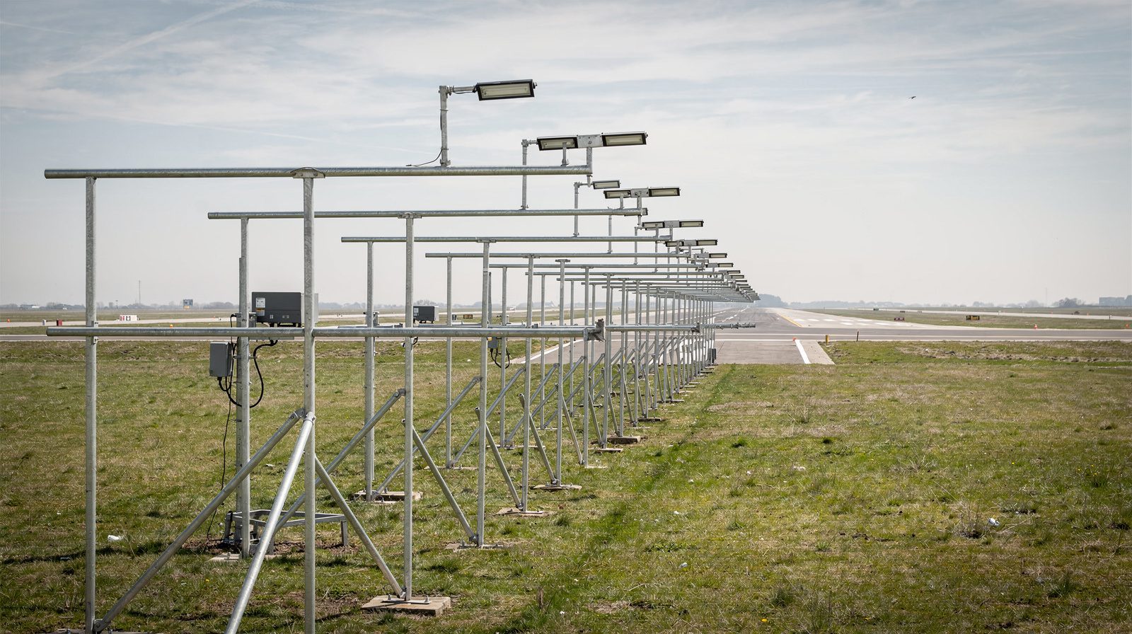
An aerodrome operator can compare each lighting system on the field with the plate for the runway. A drone inspection can measure the approach lights unit by unit. TarmacView’s approach lights inspection measures colour, relative intensity and coverage.
TarmacView does not publish plates and does not design procedures. This page covers the US plate. It makes no claim about the ICAO chart in Annex 4.
Frequently Asked Questions
- What is an approach plate?
- An approach plate is a chart that shows one instrument approach procedure, with its routes, altitudes, minima and missed approach. It is the pilot's name for what the FAA calls an instrument approach procedure (IAP) chart.
- Where is the TCH on an approach plate?
- On a US Government plate it is in the profile view, in the lower half of the profile box. A note gives the glide slope or glidepath angle and the threshold crossing height, rounded to a whole number. The note is on all ILS plates and on RNAV plates with a decision altitude.
- What is the difference between an approach plate and an instrument approach procedure?
- The procedure is the set of manoeuvres that a pilot flies. The plate is the published chart of that procedure. Some procedures have no chart. Radar approaches are printed in tabular form instead.
- What does an approach plate show?
- A US Government plate has six sections. They are the briefing strips, the planview, the missed approach icons, the profile, the minima data and the airport sketch. The sections give the route, the altitudes, the glide path, the landing minima, the missed approach and the runway layout with its lighting.
- Is approach plate still the correct name?
- Pilots still say it, but the FAA uses chart. The 2017 edition of the FAA Instrument Procedures Handbook changed instrument approach plates to instrument approach charts. AIM paragraph 5-4-5 calls them instrument approach procedure (IAP) charts.
- What do the lines under, over and around an altitude on a plate mean?
- On US Government charts, an underscore means minimum altitude, so the aircraft stays at or above it. An overscore means maximum altitude, so the aircraft stays at or below it. Both lines mean a mandatory altitude. No line means a recommended altitude for descent planning.
- What lights does an approach plate show?
- The plate shows the approach lighting system by name, with a miniature graphic and an icon. The airport sketch shows approach light symbols and notes for runway end identifier lights, runway lead-in lights and runway lights. A negative symbol marks lights that the pilot can switch on.
References
- faa-iac-4
- IAC 4, United States Government Specifications for the Flight Information Publication, Instrument Approach Procedures, 7 October 2025 Interagency Air Committee (DoD and FAA)
- faa-iph-16b-changes
- FAA-H-8083-16B, Instrument Procedures Handbook, 2017, Summary of Changes FAA
- faa-ac-150-5300-13b
- AC 150/5300-13B, Airport Design, Change 1 with errata FAA
This is a reference entry. TarmacView provides drone inspection services and doesn't sell the equipment or materials described in this glossary.