ICAO Doc 9157 Part 4: Aerodrome Design Manual, Visual Aids
What ICAO Doc 9157 Part 4 covers on aerodrome lighting, why it is guidance, how it says to check PAPI setting angles and where it mentions unmanned aircraft.
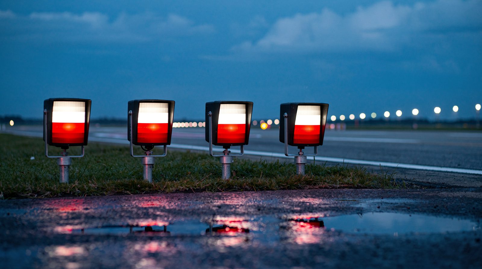
- 01 Part 4 is guidance. The Standards and Recommended Practices are in Annex 14, which points to the manual mostly in Notes, and Notes are not part of a Standard.
- 02 Paragraph 8.3.43 says an unmanned aircraft system may be used as an alternative method for measurement of PAPI settings. Paragraph 8.3.46 adds a validated visible spectrum camera and possible special authorization from the State.
- 03 Paragraph 8.3.43 calls an RTK base station necessary for high dimensional precision. Paragraph 8.3.44 computes the setting angle from the heights of the red to white transition seen from a measured distance.
- 04 In the text read, unmanned aircraft appear only in 8.3.43 to 8.3.46. The manual gives no accuracy figure for the unmanned method and names no approved system.
- 05 Amendment No. 2 of 15 September 2025 is sold separately and its changes could not be read for this page.
On this page · 10 sections
Doc 9157 Part 4 does not allow or forbid drones to check PAPI angles, because it is guidance. It does describe the method. Paragraphs 8.3.43 to 8.3.46 say an unmanned aircraft system “may be used as an alternative method for measurement of PAPI settings”, with a validated camera and possibly special authorization from the State.
Doc 9157 is ICAO’s Aerodrome Design Manual, published in six parts, and Part 4 is the one on visual aids. The fifth edition dates from 2021 and has 19 chapters and 6 appendices. Readers usually come to it for one of three things. They want the PAPI verification methods in Chapter 8, the lighting maintenance guidance in Chapter 18, or the intensity measurement methods in Chapter 19. This page says what those chapters contain and what status they carry. It does not repeat the six-part overview on the Aerodrome Design Manual glossary page.
Guidance that sits under Annex 14
The foreword says the material is closely associated with the specifications in Annex 14, Volume I, and that the manual’s main purpose is to help States implement them. Section 1.1, the introduction to Chapter 1, says the information in that chapter is for illustrative purposes and is not necessarily meant to imply ICAO approval or endorsement of the operational practices described. The foreword itself calls the contents guidance. The manual is neither a Standard nor a Recommended Practice.
The Standards and Recommended Practices are in the Annex . Its foreword says Notes give factual information or references and do not form part of the Standards and Recommended Practices. Most of the Annex’s pointers to Part 4 sit in Notes. The Note after 5.3.1.8 covers measuring the temperature of inset lights. The Note after 5.3.5.32 gives additional guidance on PAPI light unit characteristics. Note 1 after 5.3.5.46 points to Part 4 for guidance on what to do when an existing object extends above the obstacle protection surface of the system. The Note after 10.5.1 covers maintenance criteria, the site standard and a higher main beam average intensity. A value that appears only in Part 4 is a design or maintenance suggestion.
One pointer is not a Note. Footnotes to the obstacle light tables in Annex 14 Chapter 6 say that for flashing lights the effective intensity is determined in accordance with Part 4, and CS-ADR-DSN repeats that wording in its obstacle light tables. Tables form part of the Standard or Recommended Practice they accompany, so on that one point the Annex’s own tables refer to the manual’s method.
The wording is not uniform. Most paragraphs say “should” or “may”. A few say “must” or “shall”, for example 8.3.56 on installation tolerances and 8.3.60 on action when an object penetrates the obstacle protection surface. Check those against Annex 14 Chapter 5 and the EU specification before quoting them as requirements. The ICAO Annex 14 page and the EASA CS-ADR-DSN page set out those two texts.
Doc 9157 Part 4 at a glance
- Issuer
- ICAO, Aerodrome Design Manual (Doc 9157), Part 4 Visual Aids.
- Edition
- Fifth edition, 2021. The copy read lists Amendment 1 dated 12 July 2021 and Corrigendum 1 dated 13 May 2021.
- Status
- Guidance. The Standards and Recommended Practices are in Annex 14 Volume I, which refers to Part 4 mostly in Notes.
- Size
- 19 chapters and 6 appendices, from visual ground aids to the measurement of light intensity.
- PAPI
- Chapter 8, section 8.3: unit characteristics, testing, setting angles, inspection and verification, maintenance and siting.
- Unmanned aircraft
- Paragraphs 8.3.43 to 8.3.46, an alternative method for measurement of PAPI settings.
- Maintenance and measurement
- Chapter 18 on maintenance of lighting performance and Chapter 19 on measurement of light intensity.
- Amendment 2
- Dated 15 September 2025, sold separately by ICAO. The store page does not describe its changes.
What Part 4 covers
The chapters group into ground aids and markings, light characteristics, the visual slope guidance systems, runway and taxiway systems, obstacles and frangibility, and maintenance and measurement. The titles below follow the table of contents of the copy read.
| Chapters | Subject |
|---|---|
| 1 to 3 | Functional requirements of visual ground aids, markings and markers, signal area and panels |
| 4 to 7 | Light characteristics for precision approach runways and taxiways, light intensity settings, runway lead-in lighting, circling guidance lights |
| 8 | Visual approach slope indicator systems: T-VASIS in 8.2 and PAPI in 8.3 |
| 9 to 14 | Runway and taxiway lighting, surface movement guidance and control, autonomous runway incursion warning, signs, parking and docking guidance, apron floodlighting |
| 15 and 16 | Marking and lighting of obstacles, frangibility of visual aids |
| 17 | Application of approach and runway lighting systems for each category of runway |
| 18 and 19 | Maintenance of lighting performance, measurement of the light intensity of steady burning and flashing lights |
| Appendices 1 to 6 | Docking and parking guidance requirements, paints, day intensities, a graphics method, eye-to-wheel heights |
This page reads Chapters 8, 18 and 19 in detail, because they deal with checking, maintaining and measuring lights already installed.
Checking a PAPI: Chapter 8
Section 8.3 describes the PAPI as a four-unit wing bar, with the unit nearest the runway set highest and a normal difference of 20 minutes of arc between the setting angles (8.3.5). Table 8-1 gives the settings for a typical 3 degree approach: 3°30′ for unit D, 3°10′ for C, 2°50′ for B and 2°30′ for A. The manual says a satisfactory transition from white to red is not more than 3 minutes of arc deep at azimuths up to 8 degrees either side of the beam centre, and not more than 5 minutes at 15 degrees (8.3.10).
The foreword lists new fifth edition material on PAPI testing criteria, single and doublet lens designs and the inspection and verification methods that follow. It names the clinometer, the ground check, the image analysis method and automatic monitoring. The table sets out each method as the manual describes it.
The PAPI verification methods in Doc 9157 Part 4
| Method | Paragraphs | What the manual says | What it needs |
|---|---|---|---|
| Clinometer | 8.3.21, 8.3.23 | Checks the aiming angle of each unit against its own structure. It does not measure the projected beam (8.3.32). Resetting after a discrepancy is done with it (8.3.24). | The clinometer supplied with the PAPI and access to each unit |
| Ground survey | 8.3.24 to 8.3.30 | A theodolite, surveyor's rod and engineer's square, with an observer who watches the colour change. Accuracy about 3 minutes of arc. Described as a check, not a calibration technique. | A surveyor and a theodolite at the unit |
| Lift platform | 8.3.31 | Used by some States to extend the viewing distance up to 150 m. | A lift platform |
| Image analysis | 8.3.32 to 8.3.35 | A camera 10 to 15 m from the unit measures the transition zone independently of the housing, better than 1 minute of arc. Allowed as a substitute for flight checks by some States. | A tripod-mounted sensor and software |
| Checkboard | 8.3.36 to 8.3.38 | A screen on a rod 20 m ahead of each unit, marked in 1 minute steps over 5 minutes either side of the red and white line. | Eight concrete pads and a screen that is removed after the check |
| Automatic monitoring | 8.3.39 to 8.3.41 | A permanent sensor 10 m ahead of the unit alarms when the transition moves by 3 to 6 minutes of arc. Readjustment uses the checkboard. | A permanent installation per unit |
| Flight inspection | 8.3.42 | For a new installation, by the competent authority. Covers range, brilliancy control, setting angles with no gross misalignment, and compatibility with the glide path if provided. | An inspection aircraft |
| Unmanned aircraft system | 8.3.43 to 8.3.46 | An alternative method for measurement of PAPI settings. Angles come from the heights of the transition zone seen from a measured distance. | An RTK base station, a validated visible spectrum camera and possibly State authorization |
The manual gives the PAPI a maintenance routine as well. A daily check confirms that all lamps are lit and illuminated evenly, that there is no damage, that the change from red to white is coincident across the elements of a unit and that the lenses are clean (8.3.48). Monthly checks look for vehicle damage, rodents, water and insects, and realignment may be done then (8.3.49). Quarterly checks clean the reflector, lenses and filters (8.3.50). Paragraph 8.3.47 says this is a recommended routine that may be altered to suit local conditions. The PAPI inspection service page explains what a measured transition angle looks like in a protocol.
Unmanned aircraft in 8.3.43 to 8.3.46
The four paragraphs sit under the heading “Use of an unmanned aircraft system (UAS)”. Paragraph 8.3.43 says a UAS “may be used as an alternative method for measurement of PAPI settings”. It lists the parts of a typical system as the aircraft, a control or remote pilot station, a data link, possibly launch and recovery equipment, and a ground processing unit. It says an RTK base station is necessary to obtain high dimensional precision, and that the data can be viewed at the site and recorded.
Paragraph 8.3.44 describes a typical operation. The aircraft is at least 300 m from the PAPI. Vertical scanning gives the heights h1 and h2, the upper and lower limits of the red to white transition zone. The unit setting angle is then the arctangent of (h1 plus h2) divided by 2d, where d is the horizontal distance of the aircraft from the PAPI. Figure 8-24 draws the geometry. Paragraph 8.3.45 uses horizontal scanning to find the lateral limits of the system by noting where the signals from units D and A disappear.
Paragraph 8.3.46 sets the conditions. The method needs a visible spectrum camera or sensor that is “operationally validated against the perceived total image quality”, and it “may require special authorization from the competent State’s authority that has jurisdiction”.
In the text read, unmanned aircraft appear nowhere else. A search of the extracted text finds the terms only in the abbreviations list and in these four paragraphs, so the manual describes no unmanned method for runway, approach or taxiway lights. In the copy read, the pages that carry these paragraphs are marked 12/7/21, No. 1, which is the date and number of Amendment No. 1. A copy of the 2021 text without that amendment may not contain them.
Two other ICAO papers show how the paragraphs are read. A vendor paper to the 2023 SAM Implementation Group cites paragraph 8.3.43 for the point that drones are an efficient and less expensive option, and presents the company’s own drone method. A Kazakhstan information paper to the 2025 Assembly says existing ICAO material was developed with manned operations in mind and lacks procedures, performance criteria and safety parameters specific to unmanned systems. It asks ICAO to consider whether Annex 14, Doc 9137 Part 8 and Doc 9157 Part 4 need updating. Both are one party’s view, not ICAO text. The regulatory acceptance guide covers how authorities have handled drone methods.
Maintenance and measurement: Chapters 18 and 19
Chapter 18 gives guidance on Annex 14 paragraph 10.5, the preventive maintenance system for approach and runway lighting that supports Category II and III operations (18.1.2). It repeats the Annex Recommendations on in-field measurement in 18.3.8 and 18.3.9, then adds reasoning and practice.
- Why output matters. In low visibility a 50 per cent drop in light output reduces the range of a lighting aid by approximately 10 per cent, and in-pavement fittings often lose far more than 50 per cent without a good maintenance regime (18.3.3).
- What inspection cannot see. Visual inspection and maintenance schedules alone at best find lamp failures, gross misalignments and structural damage (18.4.2).
- How often. The measurement interval is set for each location. It may be weekly at some aerodromes, and monthly or longer at many once the system meets the standard (18.4.3). The Annex floor of twice a year for in-pavement lights and once a year for other lights on a CAT II or III runway is Recommendation 10.5.6, and the EU AMC repeats it.
- What the equipment records. Test equipment should measure and record the isocandela diagram, alignment and colour of each light with the lighting at 100 per cent (18.4.5). A vehicle speed above 50 km/h is generally found acceptable (18.4.4).
- Inset and elevated lights fail differently. Inset output is generally deficient because of contamination and optical faults, while elevated lighting is primarily affected by misalignment of the whole fitting (18.4.13).
- Approach lights and PAPI. Approach lighting outputs are more difficult to monitor, and an airborne inspection method using cameras and image processing offers one potential means (18.4.15). The paragraph names no platform. Paragraph 18.5.6 says regular visual flight inspections should be carried out where photometric measurement of approach lighting is not practicable, until a practicable means is found.
Chapter 19 covers how light intensity is measured. Paragraph 19.2.18 explains the site standard. All specified isocandela values are minimums, so units that exceed them can create an imbalance between systems, and an operator should know the output of the units first procured and keep later purchases at that level. The photometric measurement guide covers the field methods, and the serviceability limits guide covers the Annex 14 and EU percentages.
How EASA and the Czech L 14 cite it
The EU texts cite Part 4 mostly in guidance material. The guidance material to ADR.OPS.C.015, points (b) and (f), says further guidance on how to conduct a flight check is in Chapter 8 of Part 4 and in Chapter 5 of Part 8 of Doc 9137 (EAR for Aerodromes, pages 488 and 489). The AMC to the same points asks for flight checks of the lighting systems at least yearly, and the CS-ADR-DSN page sets out the AMC. GM1 ADR-DSN.M.655 points to Part 4 for the calculation for siting a PAPI or APAPI on a runway with ILS or MLS (page 708), and a note to Figure M-4 does the same for harmonisation of PAPI, ILS and MLS signals (page 704).
Chapter numbers need care. GM1 ADR-DSN.N.775 points to Part 4, Chapter 11 for signs (page 760). In the fifth edition Chapter 11 is on autonomous runway incursion warning and signs are Chapter 12. Confirm a chapter against the edition in hand.
The Czech L 14, effective 25 December 2025, lists all six parts of Doc 9157 among the manuals related to its specifications. Note 4 to the summary notes of its Appendix 2 sends the reader to Part 4 for the maintenance criteria for aeronautical ground lights and the site standard. Annex 14 carries the same pointer in its Note after 10.5.1 and in note 4 to its Appendix 2.
Where a drone survey fits
TarmacView’s PAPI inspection reads each unit’s transition angle from RTK-positioned drone frames of the colour change. That is the kind of measurement 8.3.43 to 8.3.46 describe. Two of their conditions are not something a provider can settle alone. The camera has to be operationally validated, and the State may require special authorization. Whether the method serves as an aerodrome’s periodic check is decided in its maintenance programme with its authority. The manual does not approve a system or set the tolerance a measurement must meet. The comparison with flight inspection sets out what each method checks, and the wider airfield lighting inspection service covers the other systems the manual treats.
What this page is based on
The text was read from a copy of the fifth edition with Amendment No. 1 and Corrigendum No. 1 hosted by the Swiss Federal Office of Civil Aviation. Short phrases are quoted and the rest is paraphrased, because ICAO holds the copyright. Amendment No. 2 of 15 September 2025 was not read, so any change it makes to Chapter 8 is not reflected here.
Frequently Asked Questions
- Is ICAO Doc 9157 Part 4 mandatory?
- No. The foreword says the material is closely associated with Annex 14 Volume I and that its main purpose is to help States implement those specifications. Section 1.1, the introduction to Chapter 1, adds that the information in that chapter is for illustrative purposes and not necessarily meant to imply ICAO approval or endorsement of the operational practices it describes. Annex 14 refers to Part 4 mostly in Notes, and its foreword says Notes are not part of the Standards and Recommended Practices.
- Does Doc 9157 Part 4 allow drones to check PAPI angles?
- It describes the method and leaves the authorization to the State. Paragraph 8.3.43 says an unmanned aircraft system may be used as an alternative method for measurement of PAPI settings. Paragraph 8.3.46 says the method requires a visible spectrum camera or sensor that is operationally validated against perceived total image quality and may require special authorization from the competent State authority. The manual is guidance, so it cannot itself authorize anything.
- How does the unmanned method in 8.3.44 compute the setting angle?
- The aircraft is positioned at least 300 m from the PAPI, and the manual's word for that position is downwind. Vertical scanning gives h1 and h2, the upper and lower limits of the red to white transition zone. The setting angle is the arctangent of (h1 plus h2) divided by 2d, where d is the horizontal distance of the aircraft from the PAPI. Paragraph 8.3.43 says an RTK base station is necessary for high dimensional precision. Paragraph 8.3.45 uses horizontal scanning to find the lateral limits of the system.
- What other ways of checking PAPI angles does Part 4 describe?
- Paragraphs 8.3.21 to 8.3.42 describe a clinometer check, a ground survey with a theodolite accurate to about 3 minutes of arc, a lift platform, an image analysis camera accurate to better than 1 minute of arc, a checkboard 20 m ahead of each unit, and a permanent sensor that alarms when the transition zone moves by 3 to 6 minutes of arc. Paragraph 8.3.42 adds a flight inspection of a new installation by the competent authority. Paragraph 8.3.24 says a ground check is not a calibration technique and that resetting is done with the clinometer.
- How often does Part 4 say a PAPI should be checked?
- It leaves the interval to the competent authority. Paragraph 8.3.20 says the authority should set a reasonable interval for ground checks and that in many circumstances a monthly alignment check of the setting angles is adequate. Paragraph 8.3.47 calls the daily, monthly and quarterly routine in 8.3.48 to 8.3.50 a recommended routine that may be altered to suit local conditions. The EU AMC separately asks for flight checks of the lighting at least yearly.
- Which edition is current, and what did Amendment No. 2 change?
- The ICAO store lists the fifth edition of 2021 at USD 284. The copy read for this page is that edition with Amendment No. 1 of 12 July 2021 and Corrigendum No. 1 of 13 May 2021 entered. The store also sells Amendment No. 2 dated 15 September 2025 separately for USD 46, and its page does not say what the amendment changes. Paragraph numbers and wording on this page follow the copy read and may differ after Amendment No. 2.
- How do EASA and the Czech L 14 cite the manual?
- Both cite it for guidance. EASA texts point to Part 4 for flight check items, PAPI siting on a runway with ILS or MLS, signs, obstacle lighting and the effective intensity of flashing lights. The Czech L 14, effective 25 December 2025, lists all six parts of Doc 9157 as related manuals and points to Part 4 in notes on the site standard and on runway distance remaining signs. One EASA reference sends the reader to Chapter 11 for signs, but in the fifth edition signs are Chapter 12, so check any chapter number against the edition in hand.
References
- icao-doc-9157-part-4-text
- Aerodrome Design Manual, Part 4: Visual Aids (Doc 9157), Fifth Edition, 2021, with Amendment No. 1 and Corrigendum No. 1 (English text, copy hosted by the Swiss Federal Office of Civil Aviation) ICAO
- icao-doc-9157-part-4-store
- Aerodrome Design Manual, Part 4: Visual Aids (Doc 9157, Part 4), 5th Edition, 2021 ICAO
- icao-doc-9157-part-4-amendment-2-store
- Aerodrome Design Manual, Part 4: Visual Aids (Doc 9157, Part 4), Amendment No. 2 dated 15/09/25 ICAO
- icao-annex-14-vol-i-text
- Annex 14, Volume I: Aerodrome Design and Operations, 9th edition, July 2022, with Amendment 18 (English text, copy hosted by the Swiss Federal Office of Civil Aviation) ICAO
- easa-ear-aerodromes
- Easy Access Rules for Aerodromes (Regulation (EU) No 139/2014), revision March 2026 EASA
- cz-l14
- L 14 Letiště (Czech aerodromes regulation), effective 25 December 2025 Úřad pro civilní letectví, Czech Republic
- icao-a42-wp-343
- A42-WP/343, Integrating drone technologies into visual aid flight checks: towards ICAO harmonization (Kazakhstan, information paper, 29/7/25) ICAO
- icao-sam-ig-30-wp-3-4
- SAM/IG/30-WP/3.4, PAPI calibration using drones (presented by FRACS/Heliper, 09/10/2023) ICAO South American Regional Office