PAPI, APAPI and VASI: What Separates Them and Which Still Count
PAPI vs VASI vs APAPI: a PAPI is a row of four units, an APAPI has two, a VASI is an older FAA bar system. Layouts, angles, and ICAO, EASA and FAA status.
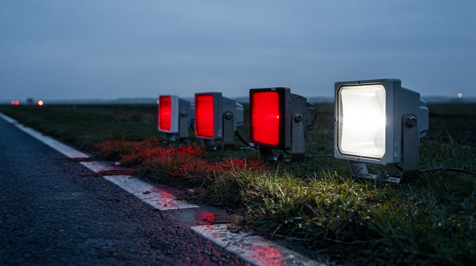
 PAPI · WING BAR · FOUR UNITS · DUSK
A PAPI is a single row of four light units beside the runway. It shows a pilot one of five red and white patterns. A VASI is an older design built from two or three bars of lights at different distances from the threshold. The FAA no longer installs it as a new facility.
An APAPI is the PAPI idea with two units and three patterns. EASA names only PAPI and APAPI as the standard systems. ICAO names them too, together with T-VASIS and AT-VASIS, and recommends discontinuing those two. Neither document lists the two-bar or three-bar VASI. This post sets out the layouts, the setting angles and the status of each in the EU, ICAO and FAA texts.
One name, two meanings
ICAO uses “visual approach slope indicator system” as the heading of section 5.3.5 of Annex 14, Volume I. Under it sit four systems: T-VASIS, AT-VASIS, PAPI and APAPI (5.3.5.2). The EU acceptable means of compliance for maintenance uses the abbreviation VASIS in the same generic way, and in the same paragraph it names PAPI and APAPI (AMC1 ADR.OPS.C.015(b) and (f), ground checks).
The FAA uses “VASI” mainly for a family of systems with red and white bars. The AIM also uses the words “visual approach slope indicator” for single-unit tri-color and pulsating systems. So “PAPI versus VASI” means one thing in an FAA document and another in an ICAO one. The VGSI glossary entry covers the general class.
How a PAPI works
Annex 14 describes a PAPI as a wing bar of four sharp transition multi-lamp units, equally spaced, on the left side of the runway unless that is physically impracticable (5.3.5.24). A second wing bar on the opposite side may be added for roll guidance. The signals are set out in 5.3.5.26:
- On or close to the approach slope, the two units nearest the runway show red and the two farthest show white.
- Above the slope, one unit shows red and three white. Further above, all four are white.
- Below the slope, three units show red and one white. Further below, all four are red.
Each unit is a colour transition device. Its beam is white above a set elevation angle and red below it, and the four units are set at four slightly different angles. The pilot reads the glide path from how many units have turned red. Red below the slope and white above it is the same rule in a VASI, so red means too low and white means too high.
How an APAPI differs
An APAPI has two units instead of four (5.3.5.25). It shows three signals: both white above the slope, one red and one white on it, both red below (5.3.5.27). That is coarser guidance than a PAPI gives.
Annex 14 provides for the choice by runway size. Where the code number is 3 or 4, a PAPI, T-VASIS or AT-VASIS shall be provided when one of the listed conditions applies, such as use by turbojet aeroplanes or misleading terrain (5.3.5.1 and 5.3.5.3). Where the code number is 1 or 2, a PAPI or an APAPI shall be provided (5.3.5.5). CS ADR-DSN.M.640(c) and (d) follow the same split for PAPI and APAPI, with the verb “should” that a certification specification uses.
An APAPI can grow into a PAPI. Annex 14 allows the APAPI unit spacing to be 9 m instead of 6 m “if greater range is required or later conversion to a full PAPI is anticipated”. In the conversion case the inner unit is then 15 m from the runway edge (Figure 5-19, note g). In FAA terms, the two-box L-881 is normally installed on runways without electronic guidance, at non-Part 139 airports, or where a serious hazard exists below the normal path, and it can be expanded to the four-box L-880 when jet operations start (AC 150/5340-30J, 7.3.6.4.5).
The setting angles
Annex 14 Figure 5-20 illustrates both systems for a 3° approach slope:
| System | Unit setting angles (3° slope) | Approach slope is |
|---|---|---|
| PAPI | 2°30’, 2°50’, 3°10’, 3°30' | the mean of the two middle angles |
| PAPI, wider on-course sector | 2°25’, 2°45’, 3°15’, 3°35' | the same mean |
| APAPI | 2°45’, 3°15' | the mean of the two angles |
The figure note says the on-course sector of a PAPI can be widened from 20’ to 30’ to harmonise the visual path with an ILS glide path closer to the threshold. The unit nearest the runway carries the highest angle. The slope itself is not fixed at 3°. Annex 14 asks only that it suits the aeroplanes using the approach (5.3.5.36). The same figure is in CS ADR-DSN.M.650.
The FAA expresses the same geometry as offsets from the chosen path. For the four-box L-880 the units, counting from the one nearest the runway, aim 30’ above, 10’ above, 10’ below and 30’ below the glide path. For height group 4 aircraft on an ILS runway the offsets are 35’ and 15’. The two-box L-881 aims 15’ above and 15’ below (AC 150/5340-30J, Tables 7-2 and 7-3). That is the same pair of offsets as the Annex 14 APAPI at 3°. A PAPI inspection checks each of these angles against the value the unit was set to, and the approach slope entry explains the angle itself.
How a VASI differs
The AIM says a PAPI “uses light units similar to the VASI but are installed in a single row of either two or four light units”. A VASI instead arranges its units in bars. In a two-bar system, the bar nearest the threshold appears white and the far bar red when the aircraft is on the path. If it is too low, both bars appear red (JO 6850.2C, Appendix E). The two-bar systems are:
- VASI-2, two units, not installed on runways used by turbojets.
- VASI-4, four units, described as the basic FAA standard.
- VASI-12, twelve units.
A three-bar VASI adds a middle bar and a second glide path for long-bodied aircraft. On the upper path, the downwind and middle bars are white and the upwind bar is red (JO 6850.2C, Table E-1). The AIM says the lower path is normally 3° and the upper one about a quarter of a degree higher. The FAA lists VASI-6 and VASI-16 for these (JO 6850.2C, Appendix E).
The transition also differs in sharpness. In a VASI, the change from red to white occurs over about a quarter of a degree, with pinkish light in between (JO 6850.2C, Appendix E). A PAPI transition must appear to occur within 3 minutes of arc to an observer at least 300 m away (Annex 14, 5.3.5.30). A quarter of a degree is 15 minutes of arc, five times wider.
Where each one stands
| ICAO Annex 14 Vol I | EU, CS ADR-DSN Issue 7 | FAA | |
|---|---|---|---|
| PAPI | Standard system, 5.3.5.24 | Standard system, M.640(b) and M.645 | Specified in JO 6850.2C chapter 5 and AC 150/5340-30J 7.5.4 |
| APAPI | Standard system, 5.3.5.25 | Standard system, M.640(b) and M.645 | Two-box L-881 type, AC 150/5340-30J |
| T-VASIS, AT-VASIS | Listed in 5.3.5.2. Use as a standard system should be discontinued as of 1 January 2020 (Recommendation 5.3.5.4) | Not listed in M.640(b) | Not named in the FAA texts read |
| Two- and three-bar VASI | Not in the list of standard systems | Not in the list | No longer installed as new. Existing equipment is supported |
The Recommendation in 5.3.5.4 sits next to a Standard in 5.3.5.3 that still names “PAPI, T-VASIS or AT-VASIS” for code 3 and 4 runways, so the text lists the system and also recommends against it. On the FAA side, JO 6850.2C says the VASI is no longer installed as a new facility and moves its criteria to an appendix “to provide technical support for existing VASI equipment”. It adds that if a VASI must be relocated, replacing it with a PAPI should be considered. The order is addressed to FAA Air Traffic Organization engineers. It is not a rule for every airport.
VASI has not vanished from FAA text. The AIM still describes it for pilots, and AC 150/5340-1M, paragraph 2.2.3.2, still speaks of a co-located PAPI or VASI when the aiming point marking is shifted. The advisory circulars are guidance. AC 150/5340-30J becomes mandatory only on projects funded through AIP grants or PFC revenue (paragraph 3). For the status of the EU and ICAO texts themselves, see our pages on Annex 14 and CS-ADR-DSN .
What this means for an inspection
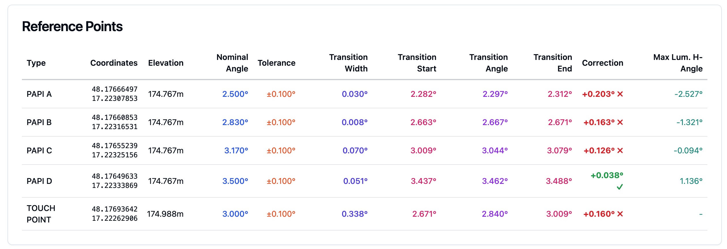
The type decides the work. A PAPI has four units and four angles to check. An APAPI has two. A VASI has bars, and its signals depend on two or three bars rather than one row. A scope should therefore state which system sits at each runway end and whether a second wing bar is fitted opposite. The PAPI inspection page describes how TarmacView measures the four units of a PAPI. If your runway has an APAPI or a VASI, say so when asking for a scope.
On a runway with an ILS , Annex 14 asks that the visual slope conforms as closely as possible to the glide path (5.3.5.37). A visual approach aid that has drifted from its set angles no longer does, and it also moves the threshold crossing height the pilot sees, because the FAA defines that height as the height of the lowest on-course signal over the threshold (AC 150/5340-30J, 7.5.4.5).
Frequently Asked Questions
- What is the difference between PAPI and VASI?
- A PAPI is one row of four light units that shows five red and white patterns. A VASI is built from two or three bars of lights at different distances from the threshold. The FAA no longer installs VASI as a new facility, and the ICAO and EASA lists of standard systems do not include the two-bar or three-bar VASI.
- What is the difference between PAPI and APAPI?
- An APAPI has two light units where a PAPI has four, so it shows three signals instead of five. Both white means above the slope, one red and one white means on it, and both red means below (Annex 14, 5.3.5.27). It gives coarser guidance. Annex 14 allows the unit spacing to be set for a later conversion to a full PAPI.
- Why does a PAPI show red and white lights?
- Each unit shows white above a set elevation angle and red below it, and the four units are set at slightly different angles. The pilot reads the approach from how many units are red. Two red and two white means on the slope, more red means too low, and more white means too high.
- How do PAPI lights work?
- A PAPI is a row of four colour transition units, equally spaced, normally on the left side of the runway (Annex 14, 5.3.5.24). The units are aimed at four angles around the approach slope. The pilot sees one of five patterns, from four white above the slope to four red below it.
- What colors does a three-bar VASI show on the upper glide path?
- On the upper glide path the downwind (nearest) and middle bars are white and the upwind (farthest) bar is red (JO 6850.2C, Table E-1). The upper path is for long-bodied aircraft. The AIM says it is normally about a quarter of a degree above the lower path.
References
- icao-annex-14-vol-i
- Annex 14 to the Convention on International Civil Aviation, Aerodromes, Volume I, Aerodrome Design and Operations, Ninth Edition, July 2022 (English text, copy hosted by the Swiss Federal Office of Civil Aviation) ICAO
- easa-ear-aerodromes
- Easy Access Rules for Aerodromes (Regulation (EU) No 139/2014) European Union Aviation Safety Agency
- faa-aim-2-1
- Aeronautical Information Manual, Chapter 2, Section 1, Airport Lighting Aids Federal Aviation Administration
- faa-jo-6850-2c
- FAA Order JO 6850.2C, Visual Guidance Lighting Systems Federal Aviation Administration, Air Traffic Organization
- faa-ac-150-5340-30j
- AC 150/5340-30J, Design and Installation Details for Airport Visual Aids Federal Aviation Administration
- faa-ac-150-5340-1m
- AC 150/5340-1M Change 1, Standards for Airport Markings Federal Aviation Administration
Founded by flight-inspection veterans who spent decades measuring PAPI lights for aviation authorities across Europe.
Learn more
Related terms
03 TERMSVisual Approach Slope Indicator (VASI)
A visual approach slope indicator (VASI) is a system of lights that gives a pilot visual descent guidance on approach. Meaning, signals, types, angles, VASI vs PAPI, standards and checks.
Precision Approach Path Indicator (PAPI)
A precision approach path indicator (PAPI) is a row of lights beside a runway. What PAPI means, what the red and white pattern shows, unit angles, siting, the APAPI, the VASI, and the checks.
Light Unit
A light unit is one light assembly of an airfield lighting system, such as one unit of a PAPI. Units per system, PAPI aiming, spacing, serviceability and LED reporting.
Further reading
03 ARTICLES
How PAPI Transition Angles Are Verified in the Field
How to verify PAPI transition angles in the field: clinometer and ground checks, flight checks and drone measurement, with the ICAO, EASA and FAA…
What a PAPI Calibration Tender Should Include
What a PAPI verification tender should include: scope, method, tolerances, report contents and frequency, with the EU, ICAO and FAA source for each.…
What ICAO Annex 14 Actually Requires of Your PAPI
The tolerances behind a PAPI protocol, what an authority looks for in the evidence, and how often the system has to be verified to stay certifiable.